Eureka AIR delivers breakthrough ideas for toughest innovation challenges, trusted by R&D personnel around the world.

Optic fiber power beam combiner and preparation method thereof

A beam combiner and power technology, applied in the coupling of optical waveguides, light guides, optics, etc., can solve the problems of poor output beam quality, unsuitable for high-power fiber lasers, and complex structure of fiber laser coherent synthesis, achieving high coupling efficiency. Effect

Inactive Publication Date: 2011-07-06
WUHAN RAYCUS FIBER LASER TECHNOLOGY CO LTD
View PDF3 Cites 27 Cited by
  • Summary
  • Abstract
  • Description
  • Claims
  • Application Information

AI Technical Summary

Problems solved by technology

The coherent combination structure of fiber lasers is complex and difficult to adjust, so it is not suitable for high-power fiber laser products
The incoherent combination of fiber laser mainly includes grating method, Bragg volume grating method, etc., but these free space components require high precision and poor stability, and are not suitable for manufacturing high-power fiber laser products
[0005] Traditional fiber combiners generally use multimode single-clad fibers to couple multiple pump sources into one output to increase output power, but the quality of the output beam is poor, so it is not suitable for combining multiple fiber lasers into one a bunch of output

Method used


Image

  • Optic fiber power beam combiner and preparation method thereof
  • Optic fiber power beam combiner and preparation method thereof
  • Optic fiber power beam combiner and preparation method thereof

Examples


Embodiment 1

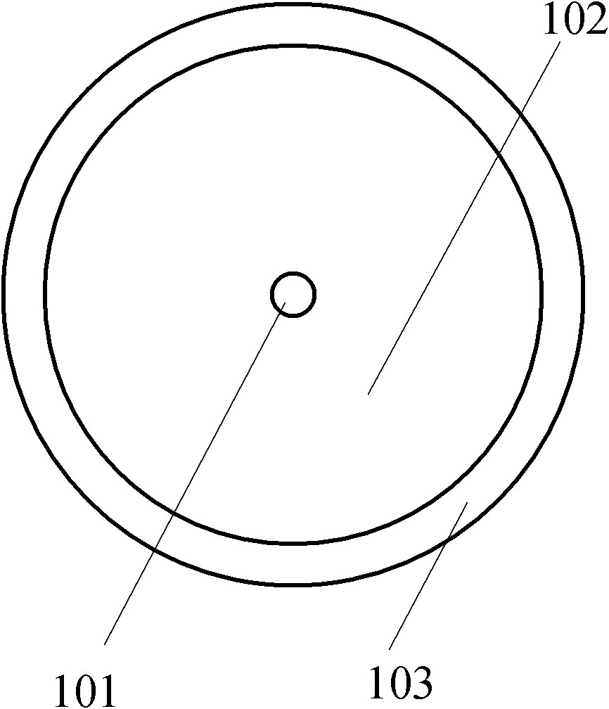
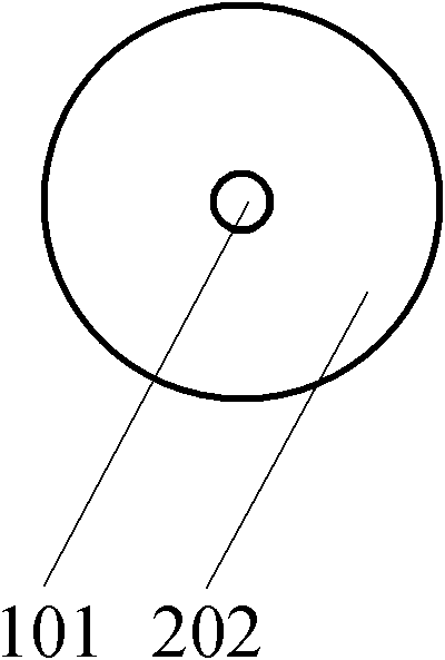
[0026] (1) will figure 1 The outer cladding 103 of the double-clad optical fiber shown is etched away, and the inner cladding layer 102 is uniformly etched to half of the original, that is, the inner cladding layer is etched from 105 μm to about 52 μm, and only the core 101 and the inner cladding layer 202 are left in the etched optical fiber. like figure 2 shown;

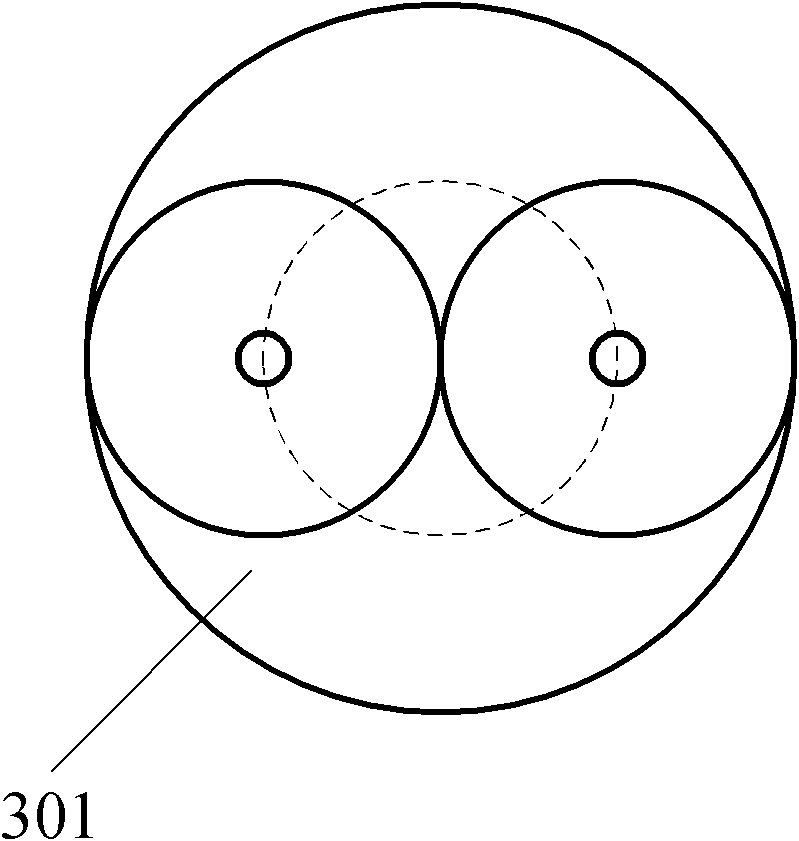
[0027] (2) Closely arrange the three input optical fibers processed in step 1 together, and put the optical fiber bundle into a quartz capillary glass tube 301, such as Figure 4 shown;

[0028] (3) uniformly heat the outside of the quartz capillary glass tube, the heating temperature is 1700 ° C, and the time is 5 minutes, so that it collapses on the optical fiber bundle;

[0029] (4) The treated end of the optical fiber bundle is melted and tapered uniformly. After the drawing is completed, the minimum diameters of the core and cladding in the taper region are 3 μm and 17 μm respectively, and then the coating...

Embodiment 2

[0033] (1) will figure 1 The outer cladding 103 of the double-clad optical fiber shown is etched away, and the cross-section of the inner cladding 102 is polished into a 120° sector, as shown in Figure 7 shown;

[0034] (2) Closely arrange the three input optical fibers processed in step 1 together, and put the optical fiber bundle into a quartz capillary glass tube 301, such as Figure 7 shown;

[0035] (3) uniformly heat the outside of the quartz capillary glass 301 tube, the heating temperature is 1700 ° C, and the time is 5 minutes, so that it collapses on the fiber bundle;

[0036] (4) The treated end of the fiber bundle is melted and tapered uniformly. After the drawing is completed, the minimum diameters of the core and cladding in the taper region are 3 μm and 35 μm respectively (sector quartz rod), and then coated;

[0037] (5) Cut the tapered end flat and spliced ​​with a large-core double-clad fiber 901. The core and inner cladding dimensions are 40 μm and 400 μ...


PUM


Abstract

The invention relates to an optic fiber power beam combiner for a large-power optic fiber laser, and a preparation method thereof. The optic fiber power beam combiner consists of n double-cladding optic fibers at an input end and a double-cladding optic fiber with a large fiber core at an output end; and the optic fiber power beam combiner is characterized by corroding outer claddings and half of inner claddings of the n double-cladding optic fibers or corroding the outer claddings of the n double-cladding optic fibers and polishing the inner claddings into fan-shaped sections of 360DEG / n; tightly arraying the treated n double-cladding optic fibers to carry out fused tapering; then coating a coating on the n double-cladding optic fibers which are treated with fused tapering; flattening the tapering end surface by cutting; and fusing with the double-cladding optic fiber with the large fiber core, and n is a natural number greater than or equal to 2. As the optic fibers at the input end and output end are double-cladding optic fibers, the optic fiber power beam combiner can be used for effectively realizing the coupling output of a plurality of optic fiber lasers and has the characteristics of being high in coupling efficiency, stable and reliable.

Description

technical field [0001] The invention belongs to the technical field of fiber lasers, relates to coupling a plurality of fiber laser light sources into one output to achieve the purpose of improving the output power of the fiber lasers, and particularly relates to a fiber power beam combiner and a preparation method thereof. Background technique [0002] Fiber lasers are the third generation of new lasers after traditional gas lasers and solid-state lasers. They have the advantages of compact structure, long life, maintenance-free, good beam quality, energy saving and environmental protection. They have been successfully used in machining, medical treatment, automobile manufacturing and military. and other fields. With the continuous expansion of its application fields, such as laser cutting and welding of medium and thick metal plates in automobile manufacturing, communication manufacturing and other industries, it is hoped that the output power of fiber lasers will reach se...

Claims


Application Information

Patent Timeline
IPC IPC(8): G02B6/24G02B6/245G02B6/255
Inventor 闫大鹏李成闵大勇李立波刘晓旭
Owner WUHAN RAYCUS FIBER LASER TECHNOLOGY CO LTD
Why Eureka
Eureka Blog
Learn More