

Heat dissipation and thermal runway dispersion protection structure in cell system
A technology of battery system and protective structure, applied in secondary batteries, circuits, electrical components, etc., can solve problems such as overheating and uneven battery temperature
- Summary
- Abstract
- Description
- Claims
- Application Information
AI Technical Summary
Problems solved by technology
Method used
Image

Examples
no. 1 example
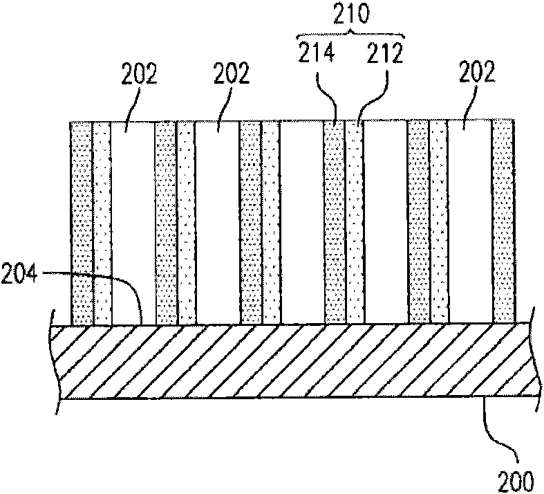
[0064] The following presents a first embodiment according to the present invention, regarding a heat dissipation and thermal runaway diffusion protection structure in a battery system (such as figure 2 shown), to block the thermal runaway spread of the battery and provide heat dissipation for the battery pack.
[0065] Please refer to figure 2 , the heat dissipation and thermal runaway diffusion protection structure of this embodiment includes a battery pack (module) casing 200 and a plurality of composite heat conducting plates 210 . A plurality of unit cells (unit cells) 202 are generally disposed in the battery pack case 200 , and only a part of the battery pack case 200 is shown in this figure to simplify the drawing. As for the composite heat conducting plate 210 , it is located in the battery pack casing 200 and contacts the battery pack casing 200 , and is placed between at least two unit cells 202 . exist figure 2 Among them, the composite heat conduction plate ...
experiment example 1
[0095] Simulate a structure similar to the first embodiment (such as Figure 8 ), which takes a square lithium battery as an example, simulating in a battery pack composed of lithium batteries 800a~g, after adding a composite heat conducting plate 802 for heat conduction and heat insulation, the battery pack protects a single lithium battery 800a from heat Efficacy of uncontrolled spread. Taking current lithium batteries as an example, the thermal runaway reaction initiation temperature (ie, SEI) of the self-heating thermal runaway reaction initiation temperature is about 80-90°C, and the thermal runaway critical temperature of the unit cell is about 150°C.
[0096]In this experimental example, the thickness of each lithium battery 800a-g is 0.5cm (this is the most commonly used thickness of square aluminum foil pack batteries at present), and the surface size of the simulated battery 800a-g is 10cm×13cm, The simulation is performed with a height of 13cm. As for the simulate...
experiment example 2
[0103] Simulate a structure similar to the third embodiment (such as Figure 10 ), wherein the size of the lithium batteries 1000a-g is the same as that of the simulation experiment example 1. The simulated composite heat conduction plate 1002 is a three-layer structure composed of two heat conduction layers 1004 sandwiching a heat insulation layer 1006 . The material, thickness and thermal conductivity of each heat conducting layer 804 and heat insulating layer 806 are the same as those of simulation experiment 1, that is, the total thickness of the heat conducting layer is 0.2 cm, and the thickness of the heat insulating layer is 0.1 cm. The thermal conduction layer of the composite heat conduction plate 1002 accounts for 2 / 3 of the thickness of the overall composite heat conduction plate, and the heat insulation layer accounts for 1 / 3 of the thickness of the overall composite heat conduction plate. According to the equation in the simulation experiment example 1, the compos...
PUM
| Property | Measurement | Unit |
|---|---|---|
| Thermal conductivity | aaaaa | aaaaa |
| Thermal conductivity | aaaaa | aaaaa |
| Thermal conductivity | aaaaa | aaaaa |
Abstract
Description
Claims
Application Information