
Furnace top structure of heating furnace

A furnace top structure and heating furnace technology, applied in the direction of the furnace crown/roof, can solve the problems of easy falling of fiber folded blocks, shortening the service life of the furnace lining, and difficult repairs, so as to reduce costs, prolong service life and facilitate replacement Effect

Active Publication Date: 2011-07-13
CHONGQING AOKEQI TECH
View PDF5 Cites 4 Cited by
  • Summary
  • Abstract
  • Description
  • Claims
  • Application Information

AI Technical Summary

Problems solved by technology

[0007] The present invention is aimed at the installation structure of the full-fiber lining of the heating furnace in the prior art, which cannot avoid the formation of gaps between adjacent fiber modules or fiber folding blocks due to the shrinkage of refractory fiber materials at high temperatures, and the flames jump up from the gaps and burn out. The anchors, screws, furnace roof steel plates and other components for fixing fiber modules or fiber folded blocks shorten the service life of the furnace lining, the furnace top fiber modules or fiber folded blocks are easy to fall off, and are difficult to repair. Provide a method to prevent fixed fiber modules or The roof structure of the heating furnace with long service life due to burnout of the metal suspenders, hanging parts, and steel beams or steel plates for hanging the furnace lining of the fiber folding block

Method used


Image

  • Furnace top structure of heating furnace
  • Furnace top structure of heating furnace
  • Furnace top structure of heating furnace

Examples


Embodiment Construction

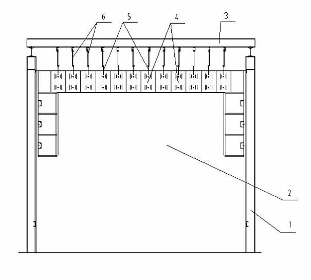
[0022] Such as figure 1 , 2 Among them, the roof structure of a heating furnace in the present invention includes a furnace body 1 of the heating furnace, the cavity in the furnace body 1 is a furnace 2, and several steel beams 3 are arranged above the furnace body 1, and the steel beams 3 The number of furnaces increases correspondingly according to the size of the furnace body 1, and the steel beams 3 with a certain interval between them, arranged in the same direction or arranged in a staggered manner, are used to set the furnace lining 4, and several furnace linings 4 are arranged (suspended) under the steel beams 3; the present invention The furnace lining 4 is an all-fiber furnace lining, which is a composite fiber containing zirconium fiber, chromium fiber, or zirconium fiber and chromium fiber. It belongs to the fiber module or fiber folding block of the prior art, has excellent high temperature resistance, and can adapt to To meet the needs of heating above ℃, the fu...


PUM


Abstract

The invention discloses a furnace top structure of a heating furnace. The furnace top structure comprises a furnace body of the heating furnace, wherein multiple steel beams are arranged above the furnace body; and furnace linings are arranged below the steel beams; the furnace top structure is characterized in that: the hanging pieces of the refractory fiber furnace linings are connected to the steel beams through hanging rods; a cavity in which the steel beams and the hanging rod are positioned is communicated with the atmosphere or communicated with air outside the furnace body through multiple vent holes; and the steel beams and the hanging rods are exposed in the air. According to the furnace top structure disclosed by the invention, each furnace lining is separately arranged and hung on the steel beam, and the upper end of the furnace lining is exposed in the air; the furnace lining can be replaced at the top of the furnace top as required, thereby realizing convenient maintenance and replacement and reducing the maintenance and replacement expenses; as the metal hanging rods, steel beams and the like for fixing the furnace linings are not closed but positioned in the air, the good radiating performance is obtained; even if flames in some areas soar upwards from gaps, the metal hanging rods, the hanging pieces, the steel beams and the like cannot be burnt, thereby prolonging the service life; and all maintenance operations are performed on the furnace top, and the maintenance and replacement are convenient.

Description

technical field [0001] The invention relates to a structure of an industrial heating furnace, in particular to a roof structure of a heating furnace for heating workpieces. [0002] Background technique [0003] In the field of metal thermal processing, when the workpiece is forged or rolled, a heating furnace is required. The workpiece is placed in the heating furnace to be heated to the required temperature, and then the thermal processing operation is performed. The heating furnace in the prior art usually adopts a full-fiber lining furnace roof, and several pieces of full-fiber lining are densely covered on the furnace roof. For a heating furnace with an operating temperature of 1200-1350 ° C, the full-fiber lining of the heating furnace can reduce the heat storage of the furnace body. (Currently used full-fiber materials are zirconium-containing fibers, chromium-containing fibers, or composite fibers of zirconium-containing fibers and chromium-containing fibers), which...

Claims


Application Information

Patent Timeline
IPC IPC(8): F27D1/02
Inventor 顾向涛
Owner CHONGQING AOKEQI TECH
Learn More