Automatic analyzing system
An automatic analysis device and cleaning solution technology, which is applied to the analysis of materials, instruments, etc., can solve the problem that the supply of cleaning solution cannot reach the predetermined amount
- Summary
- Abstract
- Description
- Claims
- Application Information
AI Technical Summary
Problems solved by technology
Method used
Image
Examples
Embodiment 1
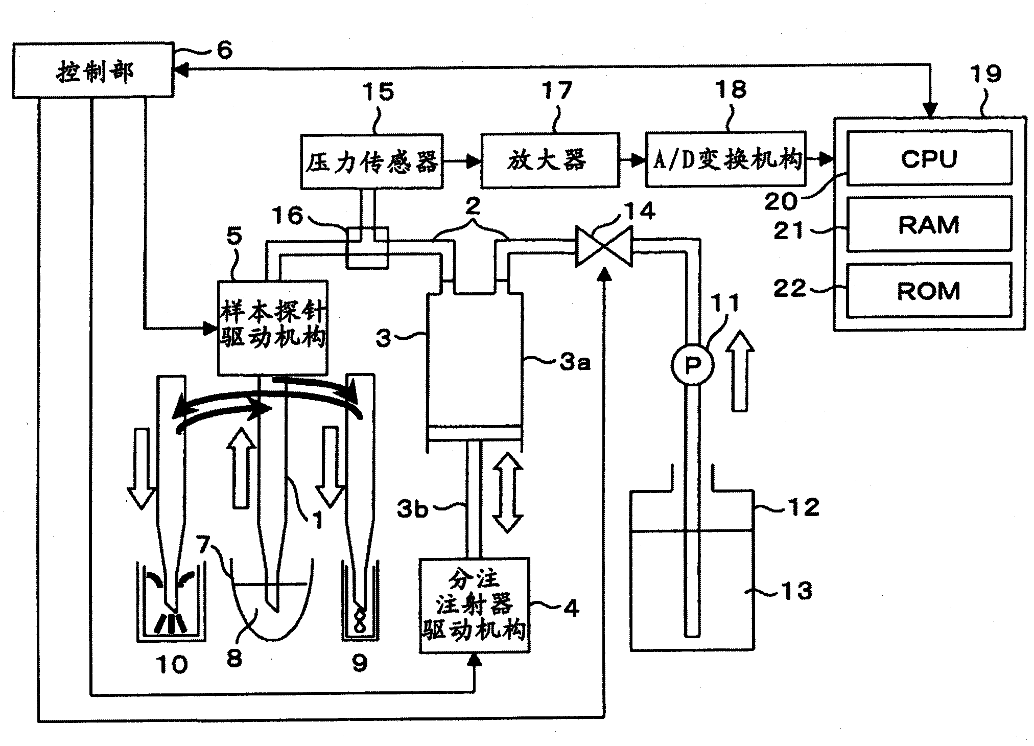
[0020] figure 1 It is an example of a configuration diagram of an automatic analyzer to which the present invention is applied.
[0021] The sample probe 1 is connected to a dispensing syringe 3 through a tube 2, and their interiors are filled with a liquid. The dispensing syringe 3 includes a cylinder 3a and a plunger 3b, and the dispensing syringe driving mechanism 4 is connected to the plunger 3b. The cylinder 3a is fixed, and the plunger 3b is driven up and down by the dispensing syringe driving mechanism 4, whereby the sample dispensing operation is performed. In addition, the sample probe driving mechanism 5 is connected to the sample probe 1, whereby the sample probe 1 can be moved to a predetermined position. In addition, the dispensing syringe drive mechanism 4 and the sample probe drive mechanism 5 are controlled by the control unit 6 .
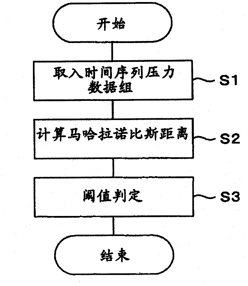
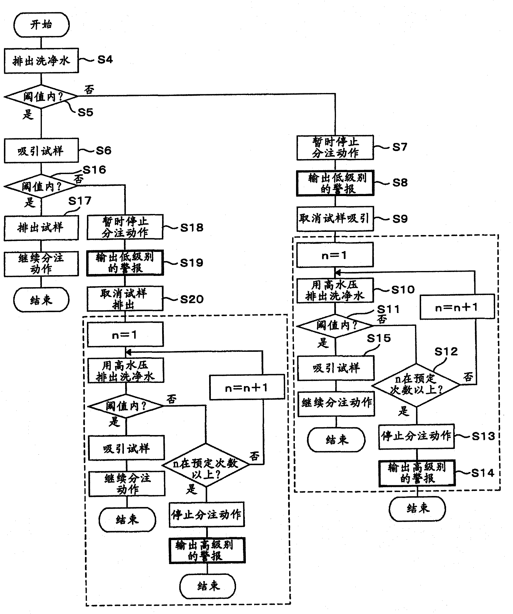
[0022] Now, the sample probe driving mechanism 5 and the sample probe 1 are lowered, and when they reach the liquid of the samp...
Embodiment 2
[0042] In recent years, automatic analyzers tend to dispensing micro-volumes, and the accuracy and reproducibility of the dispensing volumes ejected from the sample probe and the reagent probe are required.
[0043] However, the dispensing accuracy is not stable due to processing tolerances such as the inner diameter of the probe or the plunger of the syringe. Furthermore, the device tends to be miniaturized, and a relatively flexible tube such as silicon is provided inside the device. Of course, the same tube is used for connecting the sample probe from the sample syringe, and the thermal expansion of the tube makes the dispensing accuracy more unstable. That is, even dispensing accuracy errors due to conditions such as mechanical processing errors and environmental conditions that cannot be eliminated are required. In order to improve these, the operation correction can be performed based on the absolute value of the positive pressure in the washing water discharge obtained...
Embodiment 3
[0045] The life cycle of a general solenoid valve is about 3 million times, but it is expected to be used more times than that in an automatic biochemical analyzer. Furthermore, depending on the individual difference of the solenoid valve or the used liquid / environment, etc., the number of lifetimes may be shorter.
[0046] Figure 5 This is a diagram showing the phenomenon that occurs when the number of times the solenoid valve is used increases. The operation voltage here refers to the voltage at which the iron core (hereinafter referred to as plunger) in the solenoid starts to operate after the opening and closing command signal of the solenoid valve is turned ON. When the rated operating voltage is taken as 100%, the operating voltage of an unused solenoid valve is about 85%, and that of a solenoid valve with a lifetime of 3 million times is about 95%.
[0047] This operating voltage is causally related to the response time of the solenoid valve, which increases as the v...
PUM
 Abstract
Description
Claims
Application Information
 - R&D
- Intellectual Property
- Life Sciences
- Materials
- Tech Scout
- Unparalleled Data Quality
- Higher Quality Content
- 60% Fewer Hallucinations
Browse by: Latest US Patents, China's latest patents, Technical Efficacy Thesaurus, Application Domain, Technology Topic, Popular Technical Reports.
© 2025 PatSnap. All rights reserved.Legal|Privacy policy|Modern Slavery Act Transparency Statement|Sitemap|About US| Contact US: help@patsnap.com


