Two-electrode arc welding device and two-electrode arc welding method
An arc welding method and arc welding technology, which is applied in arc welding equipment, welding equipment, plasma welding equipment, etc., can solve problems such as undiscovered, and achieve the effect of improving cladding performance
- Summary
- Abstract
- Description
- Claims
- Application Information
AI Technical Summary
Problems solved by technology
Method used
Image
Examples
no. 1 Embodiment approach
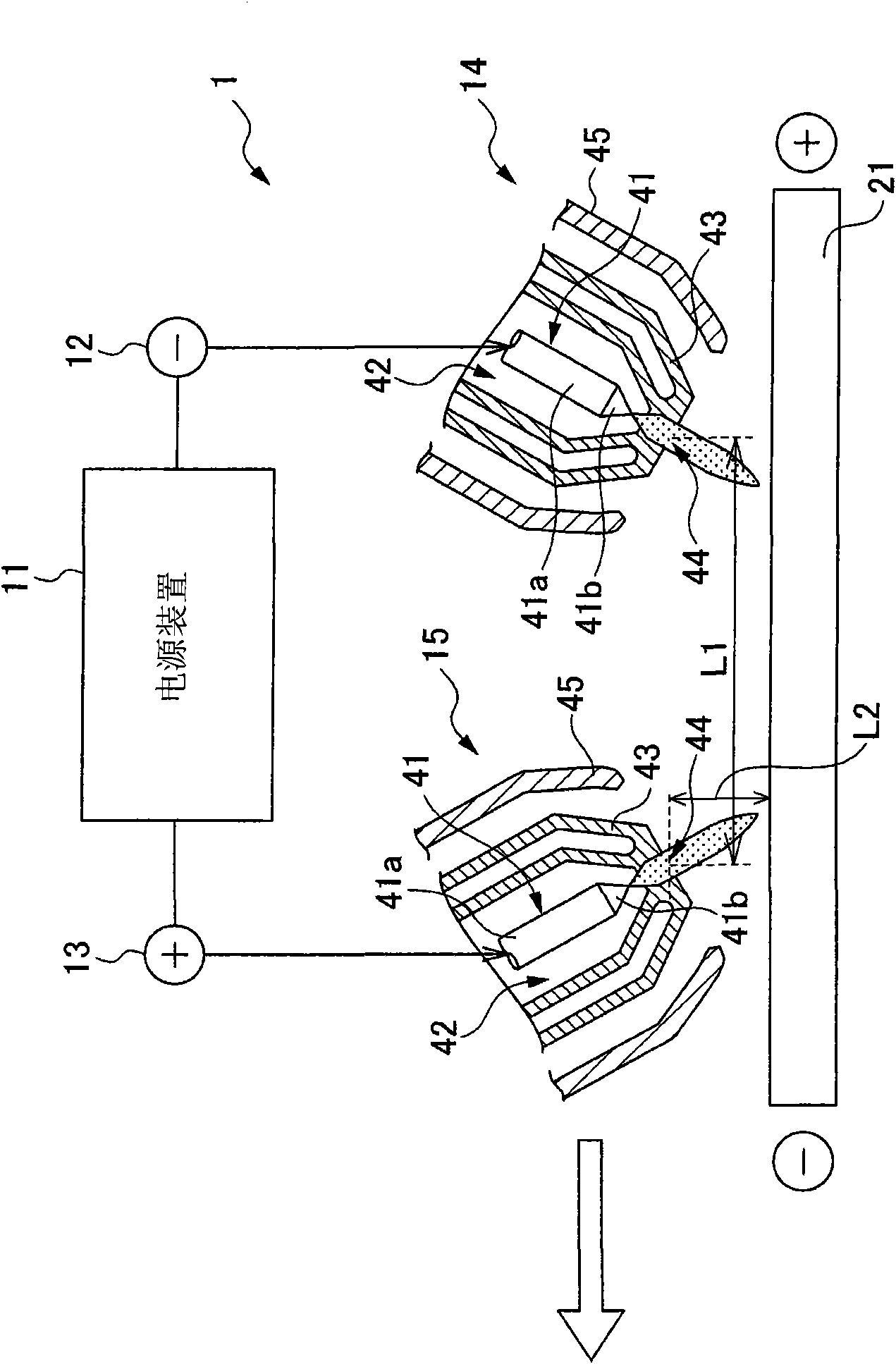
[0051] The two-electrode arc welding device 1 includes a power supply device 11 , an output terminal 12 for positive electrodes, an output terminal 13 for negative electrodes, an arc torch 14 for positive electrodes, and an arc torch 15 for negative electrodes.
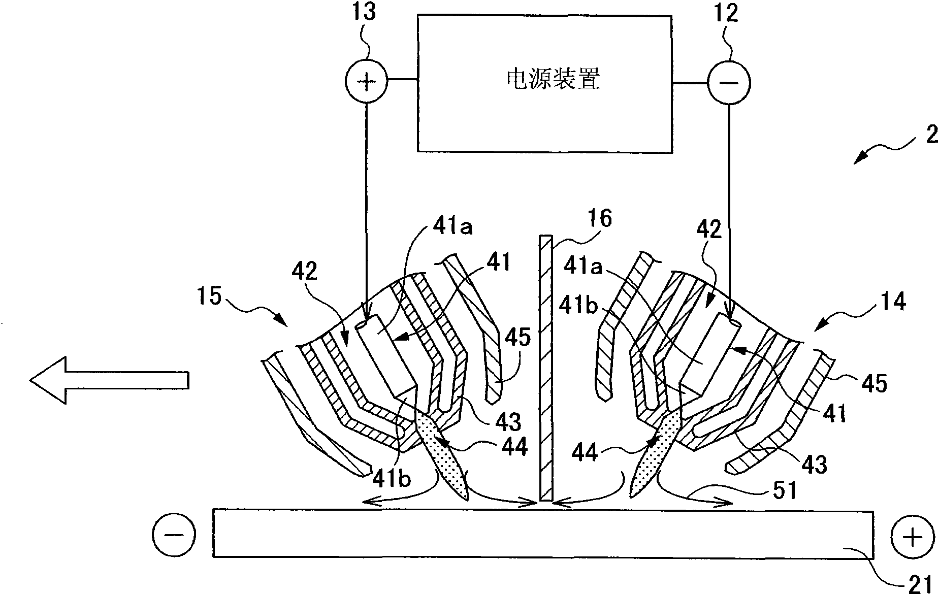
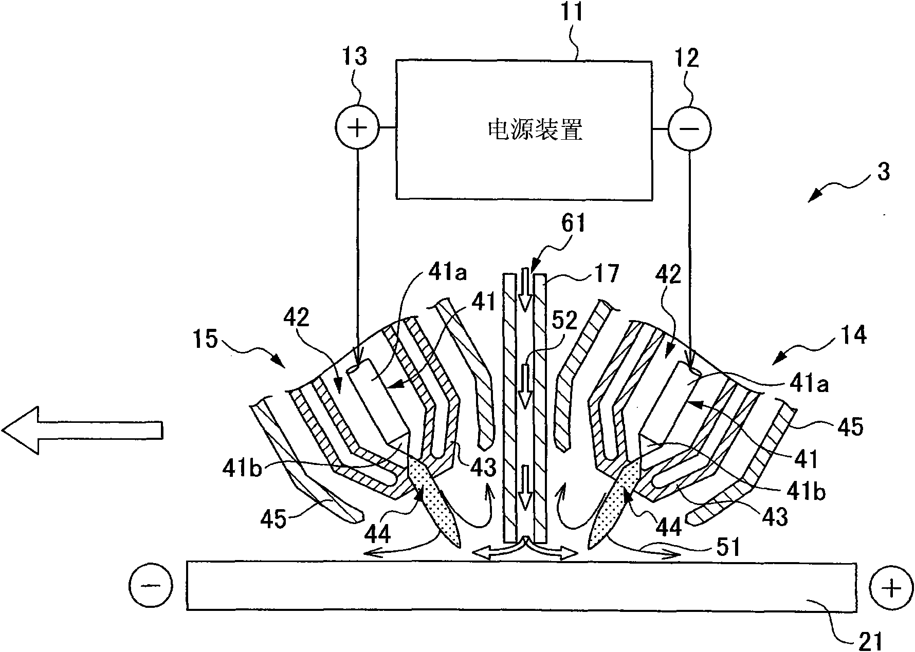
[0052] Also, in figure 1 In FIG. 2 , for the sake of brief description, only the front end portion in the vicinity of the constraining nozzle is shown for the arc torch 14 for positive electrode and the arc torch 15 for negative electrode, and the other parts are omitted from illustration. The omission of this illustration will be described later figure 2 with image 3 in the same way.
[0053] The power supply device 11 functions as a welding power source of the two-electrode arc welding device 1, and outputs a low-potential voltage (hereinafter referred to as "positive voltage") lower than that of the base material 21 from the output terminal 12 for the positive electrode, and outputs it from the output terminal ...
no. 2 Embodiment approach
[0086] Here, the distance between the electrode tabs 41b of the positive arc torch 14 and the electrode tabs 41b of the negative arc torch 15 is used to allow the preceding negative arc torch 15 to perform the preheating function of the base material 21 , the minimum distance necessary to increase the cladding depth to the desired depth exists. Hereinafter, this distance is referred to as "the cladding depth increase distance".
[0087] Such a cladding depth rise distance is often shorter than the critical distance between arcs under the conditions of the first embodiment. At this time, since the inter-arc distance L1 in the first embodiment is equal to or greater than the inter-arc critical distance under the conditions of the first embodiment, it exceeds the cladding depth increase distance.
[0088] Therefore, in the two-electrode arc welding apparatus of the first embodiment, the function of preheating the base material 21 by the preceding negative electrode arc welding t...
no. 3 Embodiment approach
[0102] As described above, the inter-arc distance L1 in the second embodiment can be shortened more than the inter-arc distance L1 in the first embodiment, and the preheating function of the preceding negative electrode arc torch 15 can be exhibited by the shortened amount.
[0103] However, if figure 2 As shown, the guide gas supplied by the gas supply unit 42 is ejected from the nozzle hole 44 at a high speed, so that the plasmaized (or easily plasmaized) gas 51 (hereinafter referred to as plasma gas 51 ) easily fills the surface of the base material 21 .
[0104] As a result, plasma gas 51 may pass between insulator 16 and base material 21 . At this time, since the plasma gas 51 has high conductivity, an arc may be generated between the positive and negative electrodes.
[0105] Therefore, in the second embodiment, it is necessary to reduce the flow rate of the guide gas used as the plasma gas 51 so as not to generate an arc between the positive and negative electrodes. ...
PUM
 Abstract
Description
Claims
Application Information
 - R&D
- Intellectual Property
- Life Sciences
- Materials
- Tech Scout
- Unparalleled Data Quality
- Higher Quality Content
- 60% Fewer Hallucinations
Browse by: Latest US Patents, China's latest patents, Technical Efficacy Thesaurus, Application Domain, Technology Topic, Popular Technical Reports.
© 2025 PatSnap. All rights reserved.Legal|Privacy policy|Modern Slavery Act Transparency Statement|Sitemap|About US| Contact US: help@patsnap.com


