Built-in cooling and filtering device

A filter device, built-in technology, applied in metal processing machinery parts, maintenance and safety accessories, metal processing equipment, etc., can solve problems such as increased maintenance costs, increased cutting oil temperature, and fragile control panels, and achieve direct savings Cost, oil temperature control precise, easy to detect the effect

Inactive Publication Date: 2011-07-20
SUZHOU YONGTIAN TECH EQUIP +1
View PDF6 Cites 0 Cited by
  • Summary
  • Abstract
  • Description
  • Claims
  • Application Information

AI Technical Summary

Problems solved by technology

[0002] Due to the high temperature generated in the cutting process, the temperature of the cutting oil will rise. The high temperature directly affects the accuracy of the workpiece and increases the defective rate of the product. The quality of the cutting oil is also easy to deteriorate, which affects the normal use of the machine tool.
At present, the refrigeration system of cutting fluid filtration equipment is connected with an external refrigerator, and the refrigerator is installed next to the filter equipment or installed outdoors. The disadvantages are: 1) It is necessary to add a pump to pump oil into the refrigerator for refrigeration, thereby increasing equipment investment costs and long-term use of electricity and maintenance costs; 2) The cooling flow and filtration flow are not equal, which will cause uneven heating and cooling of the cutting oil, resulting in thermal expansion and contraction that seriously affect the accuracy of the workpiece; 3) Installed outdoors, it is easy to be damp, The control panel is fragile, and the oil inlet and outlet pipelines are too long, which is prone to friction and heat generation, blockage and damage, etc., resulting in difficult temperature control, failure to pump oil or oil leakage, etc., resulting in increased maintenance costs; 4) Install outdoors, alarm and Faults are not easy to detect. It is often discovered when the machine tool alarms when the oil temperature rises, which will increase the defective rate of the workpiece; , heat exchange cannot achieve cooling and refrigeration; high cost, requires special maintenance, takes up space, and is not easy to install

Method used


Image

  • Built-in cooling and filtering device
  • Built-in cooling and filtering device
  • Built-in cooling and filtering device

Examples


Embodiment Construction

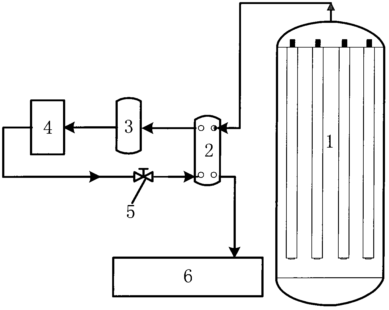
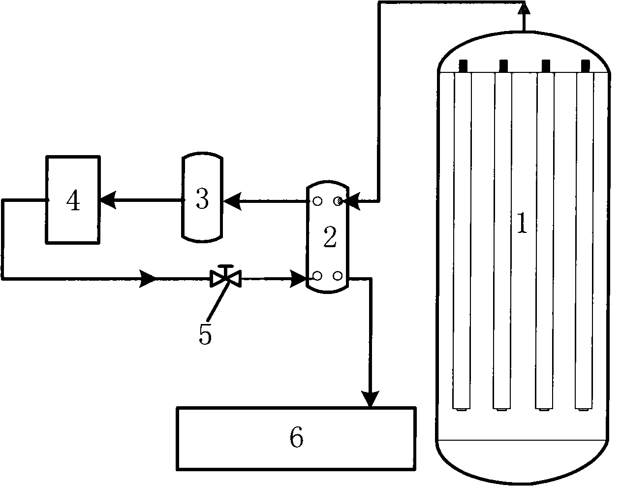
[0016] Such as figure 1 As shown, the built-in cooling and filtering device includes a filter barrel 1, a plate evaporator 2 and a clean oil pool 6. The oil outlet on the upper part of the filter barrel 1 is connected to the oil inlet of the plate evaporator 2 through an oil pipe, and the outlet of the plate evaporator 2 The oil port is connected to the clean oil pool 6 through the oil pipe; the refrigerant outlet of the plate evaporator 2 is connected to the inlet of the compressor 3 through the refrigerant pipeline, and the outlet of the compressor 3 is connected to the refrigerant inlet of the condenser 4 through the refrigerant pipeline, and the refrigerant of the condenser 4 The outlet is connected to the inlet of the throttle valve 5 through a refrigerant pipeline, and the outlet of the throttle valve 5 is connected to the refrigerant inlet of the plate evaporator 5 through a refrigerant pipeline. Among them, the refrigerant pipeline adopts copper pipe.

[0017] In specifi...


PUM


Abstract

The invention provides a built-in cooling and filtering device. An oil outlet on the upper part of a filter vat is connected with an oil inlet of a plate type evaporator through an oil pipe; an oil outlet of the plate type evaporator is communicated with a clean oil tank through an oil pipe; a refrigerant outlet of the plate type evaporator is connected with an inlet of a compressor; an outlet of the compressor is connected with a refrigerant inlet of a condenser through a refrigerant pipeline; a refrigerant outlet of the condenser is connected with an inlet of a throttling valve through a refrigerant pipeline; and an outlet of the throttling valve is connected with a refrigerant inlet of the plate type evaporator through a refrigerant pipeline. The built-in cooling and filtering device integrates refrigeration components and filtration; an oil pump is not needed to be arranged to pump clean oil to refrigeration equipment, the pump cost and agelong expenses of maintenance and electricity charge can be saved, and the cost is greatly saved; all clean cutting oil filtered out is refrigerated, so the oil temperature cannot fluctuate and uniform temperature is achieved; and the reject ratio of products cannot be improved due to expansion caused by heat and contraction caused by cold, and the refrigeration pipelines cannot be blocked due to dirty oil or impurities in the oil.

Description

Technical field [0001] The invention relates to an oil mist cooling and filtering device, in particular to a built-in cooling and filtering device. Background technique [0002] Due to the high temperature produced by the cutting process, the temperature of the cutting oil will increase. The high temperature directly affects the accuracy of the workpiece and increases the defect rate of the product. The quality of the cutting oil is also prone to deterioration, affecting the normal use of the machine tool. At present, the cooling system of the cutting fluid filtering equipment is an external refrigerator. The refrigerator is installed beside the filtering equipment or installed outdoors. The disadvantages are: 1) It is necessary to add a pump to pump the oil into the refrigerator for cooling, thereby increasing the equipment investment cost And the electricity and maintenance costs for many years of use; 2) The cooling flow and the filtering flow are not equal, which will cause u...

Claims


Application Information

Patent Timeline
Patent Type & Authority Applications(China)
IPC IPC(8): B23Q11/12B23Q11/00
Inventor 郑添全
Owner SUZHOU YONGTIAN TECH EQUIP
Why Eureka
Try Eureka