Device for testing rheological properties of magnetorheological fluid

A technology of magnetorheological fluid and rheological properties, applied in flow characteristics, measuring devices, instruments, etc., can solve the problems of increased volume ratio concentration of magnetorheological fluid, large amount of magnetorheological fluid, wall slip effect, etc. , to achieve the effect of strong magnetic field, good verticality and uniformity, and low heat generation

Inactive Publication Date: 2011-07-20
NINGBO UNIV
View PDF6 Cites 22 Cited by
  • Summary
  • Abstract
  • Description
  • Claims
  • Application Information

AI Technical Summary

Problems solved by technology

Although the pipe flow mode test can obtain a higher shear rate, the polarized suspended particles are easy to gather in the pipe under the action of a higher magnetic field, while the mother liquor flows out along the pipe, resulting in the volume ratio of the magnetorheological fluid in the pipe The local increase of the concentration will make the measurement result higher, and it will also produce the wall slip effect; the concentric cylinder rotation test will produce

Method used


Image

  • Device for testing rheological properties of magnetorheological fluid
  • Device for testing rheological properties of magnetorheological fluid
  • Device for testing rheological properties of magnetorheological fluid

Examples


Embodiment Construction

[0016] The present invention will be further described in detail below in conjunction with the accompanying drawings and embodiments.

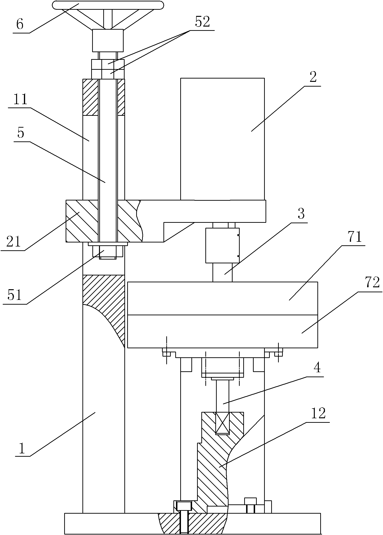
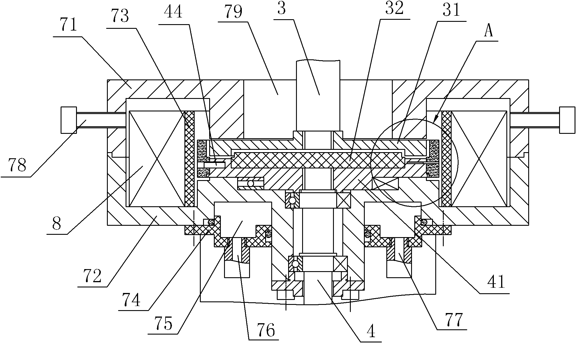
[0017] As shown in the figure, a test device for the rheological properties of magnetorheological fluid includes a bracket 1, a motor 2, a rotating shaft 3, a stationary shaft 4, a screw rod 5, a hand wheel 6, a motor bracket 21 and an upper cover 71, The housing formed by the lower cover 72, the bracket 1 is provided with a lifting hole 11, the upper end of the screw mandrel 5 is fixedly connected with the hand wheel 6, the screw mandrel 5 extends into the lifting hole 11 and is screwed with the motor bracket 21, the screw mandrel 5 The upper end of the screw rod 5 is screwed with a double nut 52, the lower end of the screw rod 5 is screwed with a positioning nut 51, the motor 2 is fixedly connected on the motor bracket 21, the lower cover 72 is fixed on the bracket 1, and the lower end of the rotating shaft 3 stretches into the housing and T...


PUM


Abstract

The invention discloses a device for testing rheological properties of magnetorheological fluid, comprising a support, a motor, a rotating shaft, a static shaft and a shell. The device is characterized in that the lower end of the rotating shat extends into the shell and the lower end part of the rotating shaft is fixedly provided with a rotating disc, the upper end of the static shaft extends into the shell and the upper end part of the static shaft is fixedly provided with a static disc, a magnetic isolation disc and an annular magnetorheological fluid cavity are arranged between the rotating disc and the static disc, a sealing ring is sleeved on the static disc, the shell is internally provided with a magnetic isolation ring and an exciting coil, the magnetic isolating ring is arrangedbetween the sealing ring and the exciting coil, the support is fixedly provided with a torque sensor, the lower end of the static shaft is connected with the torque sensor, and the upper end of the rotating shaft is connected with the output shaft of the motor. The device disclosed by the invention has the advantages that: the magnetorheological fluid cavity is arranged outside the magnetic isolation disc, thus the edge gathering effect of the magnetorheological fluid to be tested is reduced, and the consumption of the magnetorheological fluid is reduced; and the magnetorheological fluid cavity is arranged at the middle part of the exciting coil, thus a magnetic field at the magnetorheological fluid to be tested is strongest, the verticality and uniformity of the magnetic field are good, and the heat productivity is low.

Description

technical field [0001] The invention relates to the field of research on the properties of magnetorheological fluids, in particular to a testing device for the rheological properties of magnetorheological fluids. Background technique [0002] Magnetorheological fluid behaves as a low-viscosity flowable Newtonian fluid under zero magnetic field, while suspended particles are polarized under the action of an external magnetic field to form a chain-like columnar structure parallel to the magnetic field, which prevents the flow of fluid As a result, the viscosity of the suspension increases sharply, and the shear yield stress also increases approximately linearly, showing a property similar to that of a solid. When the external magnetic field is removed, it quickly returns to its original flow properties. Therefore, shear yield stress and viscosity are the main performance parameters of magnetorheological fluid, which characterize the degree of solidification of this material un...

Claims


Application Information

Patent Timeline
IPC IPC(8): G01N11/14
Inventor 任志胜胡利永郑堤詹建明黄超兵
Owner NINGBO UNIV
Why Eureka
Try Eureka