LED device with improved LED color rendering index (CRI) and manufacturing method thereof

A technology of LED devices and color rendering index, which is applied in the direction of semiconductor devices, electrical components, circuits, etc., can solve the problems of poor color rendering index of luminous spectrum, and achieve the effect of improving color rendering index, improving luminous flux, and warm color

Inactive Publication Date: 2011-07-20
SHAANXI UNIV OF SCI & TECH
View PDF5 Cites 7 Cited by
  • Summary
  • Abstract
  • Description
  • Claims
  • Application Information

AI Technical Summary

Problems solved by technology

But at the same time, the color rendering index of traditional LED luminous spectrum is relatively poor. Therefore, it is very important to effectively improve the color rendering index of LED while effectively improving LED light efficiency, luminous flux, brightness, etc.

Method used


Image

  • LED device with improved LED color rendering index (CRI) and manufacturing method thereof

Examples


Embodiment approach 1

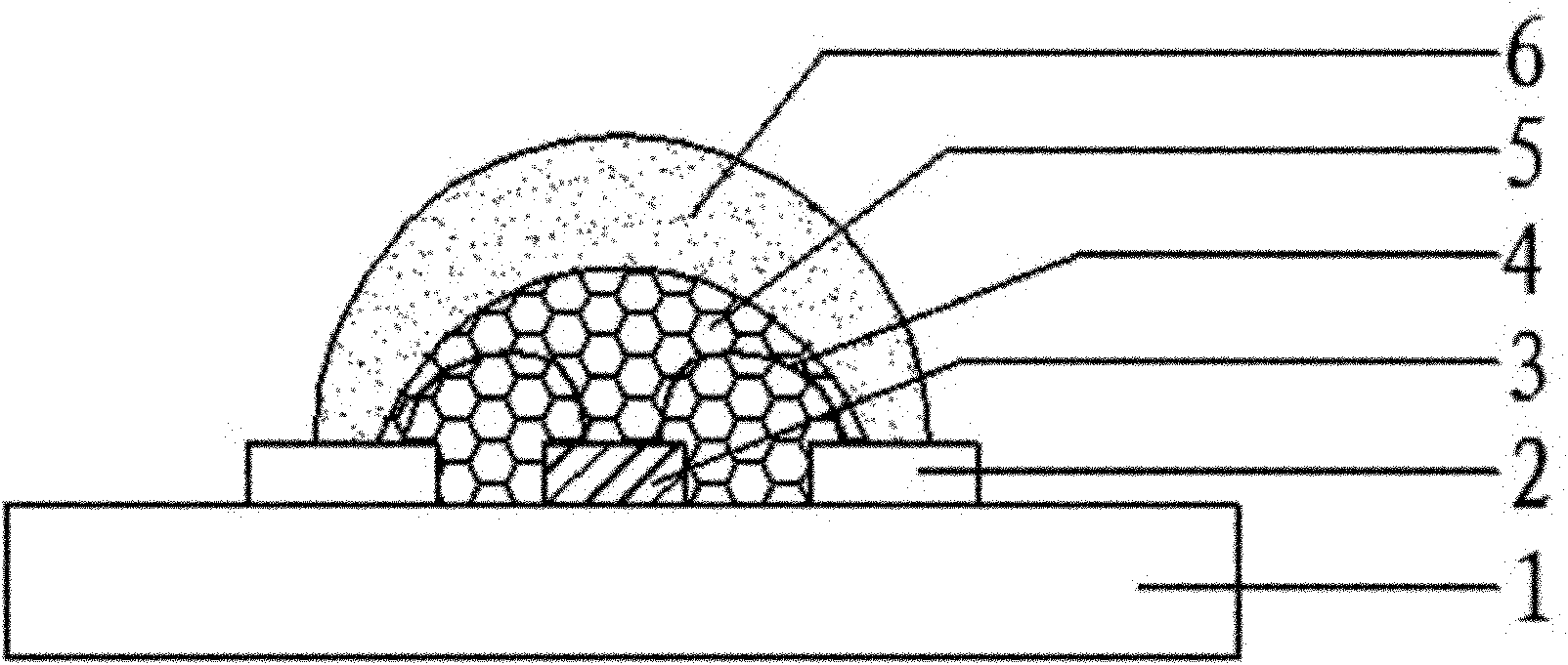
[0021] 1. Chip inspection: inspect the LED chip 3 to check whether it meets the specifications;

[0022] 2. Crystal expansion: use a crystal expansion machine to expand the film of the bonded LED chip 3, so that the distance between the LED chips 3 becomes larger, which is convenient for spinning;

[0023] 3. Glue dispensing: Dot insulating glue on the place where the LED chip 3 needs to be placed on the LED bracket 1, so as to facilitate the connection of the LED chip 3;

[0024] 4. Thorn crystal and solid crystal: stab the expanded LED chip 3 on the LED bracket 1 with a crystal pen and fix it with silver glue;

[0025] 5. Welding gold wire: connect LED chip 3 and electrode pin 2 with gold wire 4;

[0026] 6. Dot phosphor powder doped with organic material: Dot phosphor powder doped with organic material on the surface of LED chip 3 and the area between the LED chips;

[0027] 7. Drying: Dry the fluorescent powder doped with organic materials in a drying oven to form a silv...

Embodiment approach 2

[0032] 1. Chip inspection: inspect the LED chip 3 to check whether it meets the specifications;

[0033] 2. Crystal expansion: use a crystal expansion machine to expand the film of the bonded LED chip 3, so that the distance between the LED chips 3 becomes larger, which is convenient for spinning;

[0034] 3. Glue dispensing: Dot insulating glue on the place where the LED chip 3 needs to be placed on the LED bracket 1, so as to facilitate the connection of the LED chip 3;

[0035] 4. Thorn crystal and solid crystal: stab the expanded LED chip 3 on the LED bracket 1 with a crystal pen and fix it with silver glue;

[0036] 5. Welding gold wire: connect LED chip 3 and electrode pin 2 with gold wire 4;

[0037] 6. Dot the phosphor powder: Dot the phosphor powder on the surface of the LED chip 3 and the area between the LED chips 3;

[0038] 7. Drying: drying the phosphor powder in a drying oven to form a phosphor powder layer 5;

[0039] 8. Add organic material encapsulating gl...


PUM


Abstract

The invention provides an LED device with an improved LED color rendering index (CRI) and a manufacturing method thereof. The LED device comprises an LED support (1), an electrode pin (2), an LED chip (3), a gold line (4), a fluorescent powder layer (5) and an encapsulation layer (6), wherein the electrode pin (2) and he LED chip (3) are fixed on the upper surface of the LED support (1), the gold line (4) is used for connecting the LED chip (3) and the electrode pin (2), the fluorescent powder layer (5) is coated on the LED chip (3) and the encapsulation layer (6) is coated on the fluorescent powder layer (5), and the fluorescent powder layer (5) or the encapsulation layer (6) is doped with organic materials. In the invention, the organic materials is added to an LED structure, so that light emitted through the LED chip can effectively excite the organic material and enable the organic material to be subjected to photoluminescence so as to generate a light spectrum with a better CRI, and thus, the LED CRI is effectively improved. In addition, the organic materials are relatively diverse in types, relatively cheap in price, more easy to prepare and large in spectrum adjustability, therefore, a better application value can be achieved for the practical production of the LED industry.

Description

technical field [0001] The invention relates to an LED device and a preparation method thereof, in particular to an LED device with improved LED color rendering index and a preparation method thereof. Background technique [0002] Light-emitting diode (LED) is a solid-state semiconductor device that can directly convert electrical energy into light energy. With the development of LED technology, it has a wide range of uses and many advantages, and its advantages are gradually emerging, such as: the luminous brightness is significantly improved , The life is greatly extended, the volume is relatively small, the power consumption is low, the heat dissipation is low, energy saving and environmental protection, sturdy and durable, and the response time is short. Therefore, LED is considered to be a kind of green lighting source that is most likely to enter the lighting field. [0003] The core part of the LED is the PN junction. When the injected electrons and holes recombine a...

Claims


Application Information

Patent Timeline
Patent Type & Authority Applications(China)
IPC IPC(8): H01L33/48H01L33/50H01L33/56H01L33/00
Inventor 张方辉毕长栋张麦丽马颖
Owner SHAANXI UNIV OF SCI & TECH
Why Eureka
Try Eureka