Miniature microstrip antenna

A microstrip antenna and antenna technology, applied in the resonant antenna, radiating element structure and other directions, can solve the problems of reduced efficiency, impedance matching dependence, narrow bandwidth, etc., to achieve the effect of reduced size, small vertical size, and increased bandwidth

Active Publication Date: 2011-07-20
ZTE CORP
View PDF2 Cites 18 Cited by
  • Summary
  • Abstract
  • Description
  • Claims
  • Application Information

AI Technical Summary

Problems solved by technology

The resonant frequency of the antenna mainly depends on the thickness and position of the short-circuit probe, and its disadvantages are: impedance matching greatly depends on the position of the short-circuit probe and its distance from the feeding point, which is not conducive to production and narrow bandwidth
The main disadvantages are: strong surface waves are excited, large surface losses, reduced efficiency, and narrow bandwidth
Its characteristics: As the length of the slot increases, the resonant frequency of the antenna decreases, and the size of the antenna decreases, but excessive reduction in size will cause a sharp deterioration in performance, especially the bandwidth and gain. How to break the two limitations of gain and bandwidth, development Practical, easy-to-tune antennas of this type are yet to be further studied

Method used


Image

  • Miniature microstrip antenna
  • Miniature microstrip antenna
  • Miniature microstrip antenna

Examples


Embodiment Construction

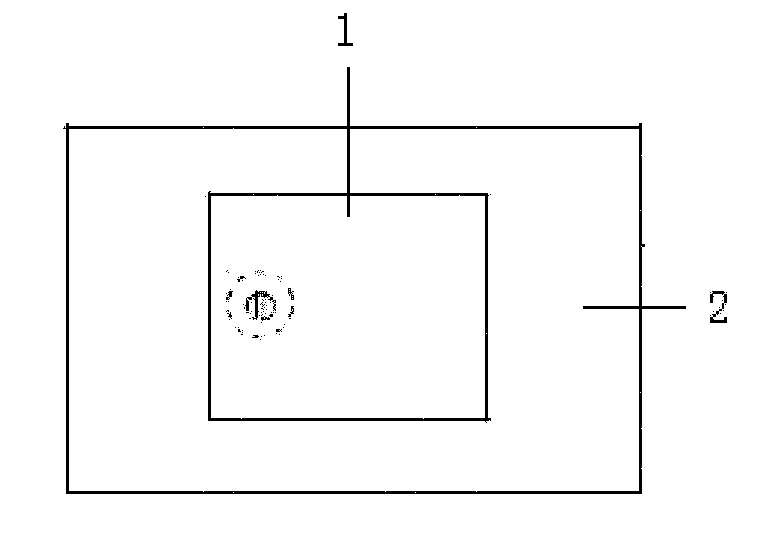
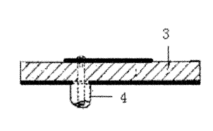
[0027] The technical scheme of the present invention utilizes the resonance characteristics of multiple small resonant rings, which are combined and placed in the substrate of the microstrip antenna, so that the size of the microstrip antenna can be greatly reduced, and the bandwidth of the antenna can be increased at the same time.

[0028] The working principle of the technical solution of the present invention is that the microstrip antenna model regards the rectangular microstrip patch as a transmission line resonator that does not change along the transverse direction, and the field changes along the longitudinal standing wave. The radiation is mainly produced by the fringe field at the open end, so the microstrip antenna It can be expressed as two parallel slots. In order to meet the phase requirements at both ends, the longitudinal field length of the microstrip antenna must reach half a wavelength. However, after loading the resonant unit in the dielectric substrate, a r...


PUM


Abstract

The invention discloses a miniature microstrip antenna, which comprises a microstrip patch, a grounding part, a medium substrate, a feeder line and a resonant cell. The medium substrate is positioned between the microstrip patch and the grounding part; the resonant cell is arranged in the medium substrate; and the feeder line is electrically connected with the resonant cell. In the technical scheme, compared with the common microstrip antenna, the microstrip antenna loaded with a small resonant ring has the advantages that: the longitudinal size of the common microstrip antenna is about half of the wavelength, and after the substrate is loaded with the small resonant ring, the longitudinal size of the microstrip antenna can be made smaller, so that the size of the microstrip antenna can be greatly reduced, and the bandwidth can be increased.

Description

technical field [0001] The invention relates to the technical field of antennas, in particular to a miniaturized microstrip antenna. Background technique [0002] The traditional microstrip antenna is on a thin dielectric substrate, one side is attached with a thin metal layer as the grounding part, and the other side is made of a certain shape metal patch by photolithography and etching, and the microstrip line or coaxial probe is used to pair Antenna composed of patch feed. [0003] Traditional microstrip antenna miniaturization design methods mainly include the following: [0004] 1. Antenna loading, load a short-circuit probe on the microstrip antenna, and introduce a coupling capacitor into the resonant cavity through the short-circuit probe close to the feed point to achieve miniaturization. The resonant frequency of the antenna mainly depends on the thickness and position of the short-circuit probe. Its disadvantages are: impedance matching greatly depends on the po...

Claims


Application Information

Patent Timeline
Patent Type & Authority Applications(China)
IPC IPC(8): H01Q9/04H01Q1/38
Inventor 刘洋
Owner ZTE CORP
Why Eureka
Try Eureka