
Failure guiding safety principle-based contactor automatic switching control method

A safety-oriented, contactor-oriented technology, applied in the direction of emergency power supply arrangements, electrical components, circuit devices, etc., can solve problems such as contactor loosening, fault expansion, equipment input power failure, etc., to reduce maintenance costs and maintenance difficulties, reduce Potential safety hazards of circuits and effects of high power supply reliability

Active Publication Date: 2014-06-11
BEIJING DINGHAN TECH GRP CO LTD
View PDF1 Cites 0 Cited by
  • Summary
  • Abstract
  • Description
  • Claims
  • Application Information

AI Technical Summary

Problems solved by technology

[0005] (1) The failure of the board where the control circuit is located may cause the device to power down. At this time, no control signal is sent out, and the drive circuit will release the two contactors for power supply, which will eventually cause the device to power down.
It leads to the expansion of faults, which does not conform to the principle of fault-oriented safety;
[0006] (2) The control board cannot realize online program upgrade
At present, control boards are often controlled by programmable smart devices, and programmable devices often have upgrade needs, but after the software is upgraded, they need to be restarted. When restarting, the smart board cannot send a control signal for the contactor to pull in, which will cause the contactor to loosen. off, the device input is powered off, and online software upgrades cannot be realized

Method used


Image

  • Failure guiding safety principle-based contactor automatic switching control method
  • Failure guiding safety principle-based contactor automatic switching control method

Examples


Embodiment Construction

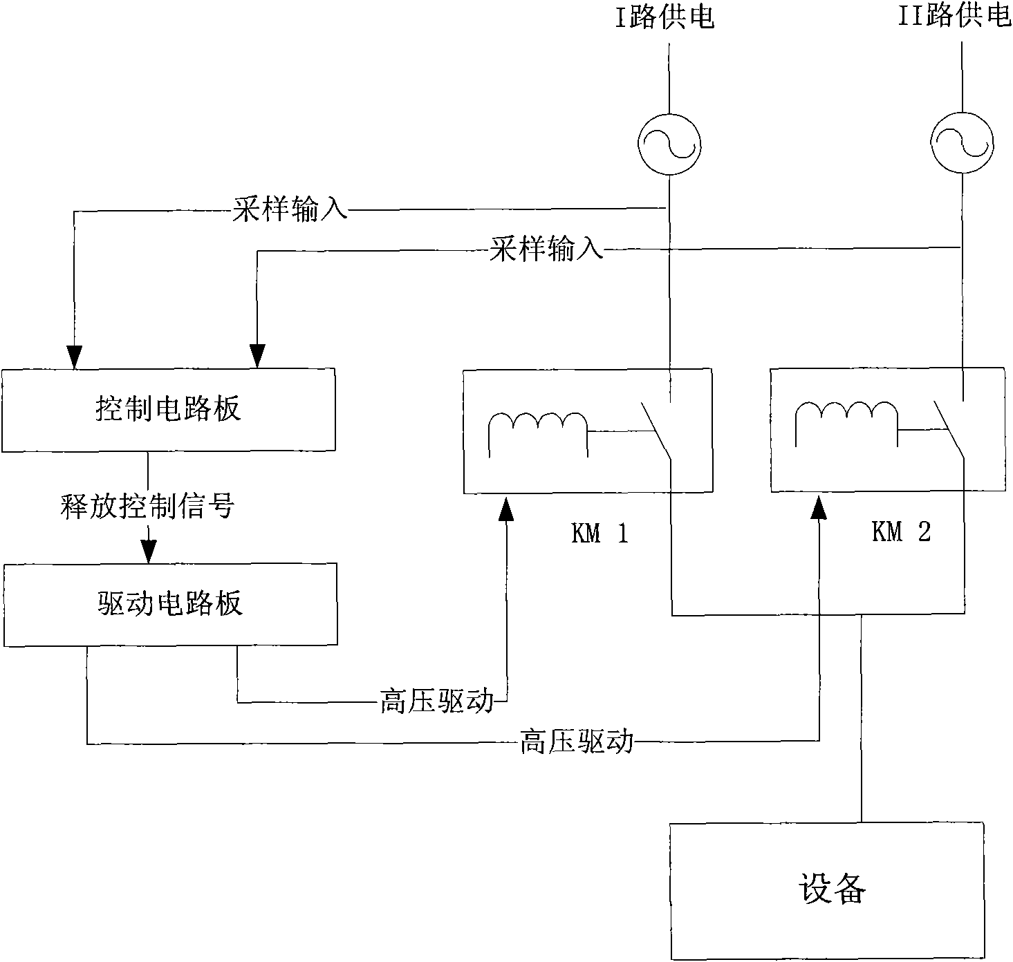
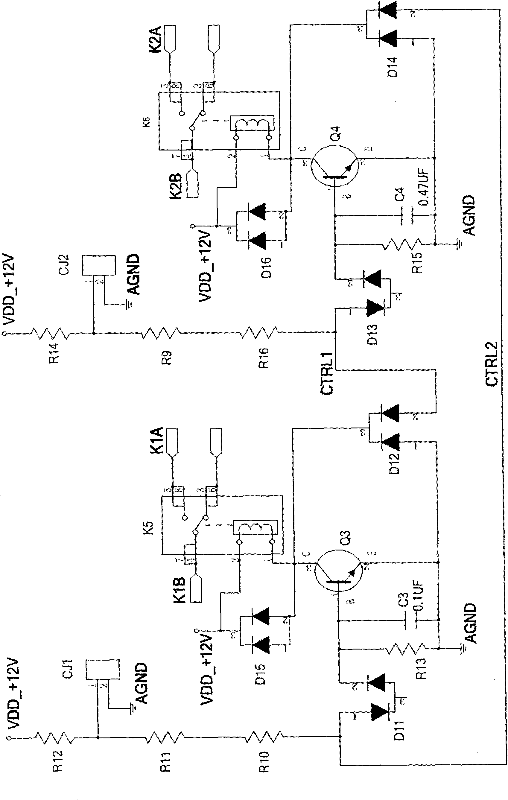
[0017] A specific embodiment of the present invention, which is based on figure 1 In the power supply system structure shown, the contactors KM1 and KM2 are respectively connected in series in the main and standby circuits, and the control circuit is separated from the drive circuit. When the control circuit sends a signal to the drive circuit, the drive circuit releases the corresponding contactor; The structure diagram of the specific contactor drive circuit is as follows: figure 2 shown.

[0018] In the figure, K5 and K6 are the control relays of contactors KM1 and KM2 respectively. When K5 is closed, K1A and K1B are connected, and contactor KM1 is closed. When K6 is closed, K2A and K2B are connected, and contactor KM2 is closed. combine. CJ1 and CJ2 are control signal input ports. When the internal pins 1 and 2 are turned on, the control contactor is released, and when pins 1 and 2 are disconnected, the control contactor is pulled in.

[0019] The circuit operation flo...


PUM


Abstract

The invention discloses a failure guiding safety principle-based contactor automatic switching control method. Contactors are connected in series into a main circuit and a standby circuit respectively, and a control circuit is separated from a driving circuit. When the control circuit transmits a signal to the driving circuit, the driving circuit releases a corresponding contactor; and the driving circuit forms interlocking between two contactor driving circuits by adopting diodes and triodes, and when the two contactors do not receive a releasing signal, only a current contactor is kept in an off state, and the other contactor is not switched off. By the method, the separation of a high voltage circuit from a low voltage circuit and the separation of a device with long service life from a quick-wearing device are realized, electromagnetic interference between the high voltage circuit and the low voltage circuit and between the device with the long service life and the quick-wearing device is reduced, potential safety hazards of the circuits are reduced, and simultaneously, maintaining cost and maintaining difficulties are reduced. When a control board fails, a power supply system can maintain an original power supply state, and the software upgrading of the control board may not cause the interrupt of power supply, so higher power supply reliability is achieved.

Description

technical field [0001] The invention belongs to the field of industrial electrics, and in particular relates to a contactor automatic switching control method based on the principle of fault-oriented safety. Background technique [0002] Generally, important equipment is equipped with a main power supply and a backup power supply. Normally, it is powered by the main power supply with high reliability. When the main power supply fails, the main power switch is turned off, and the backup power switch is turned on. This ensures that the power supply of the device is not interrupted. [0003] Since there may be phase and voltage differences between the two power supplies for the equipment, the two power supplies cannot be closed at the same time to prevent the circulation of the two power supplies and damage the power supply system. However, the longer the two switches are turned off at the same time, the longer the power-off time of the equipment, and even cause the equipment ...

Claims


Application Information

Patent Timeline
Patent Type & Authority Patents(China)
IPC IPC(8): H02J9/06
Inventor 刘延
Owner BEIJING DINGHAN TECH GRP CO LTD
Learn More