Method and device for detecting optical power of passive optical network (PON) and PON system

An optical power detection and passive optical network technology, which is applied in the field of passive optical networks, can solve the problems of misjudgment, error, and limited optical power measurement accuracy of optical modules in optical distribution networks, so as to avoid misjudgments and ensure measurement accuracy. Effect

Inactive Publication Date: 2011-07-20
HUAWEI TECH CO LTD
View PDF3 Cites 36 Cited by
  • Summary
  • Abstract
  • Description
  • Claims
  • Application Information

AI Technical Summary

Problems solved by technology

[0004] However, due to the limited optical power measurement accuracy of existing optical modules, there may be a certain deviation between the received optical power value P2 of the optical network unit obtained through optical power detection and the actual received optical power value...

Method used


Image

  • Method and device for detecting optical power of passive optical network (PON) and PON system
  • Method and device for detecting optical power of passive optical network (PON) and PON system
  • Method and device for detecting optical power of passive optical network (PON) and PON system

Examples


Embodiment Construction

[0018] The optical power detection method, system, and device for a passive optical network provided by the embodiments of the present invention are described in detail below in conjunction with specific embodiments.

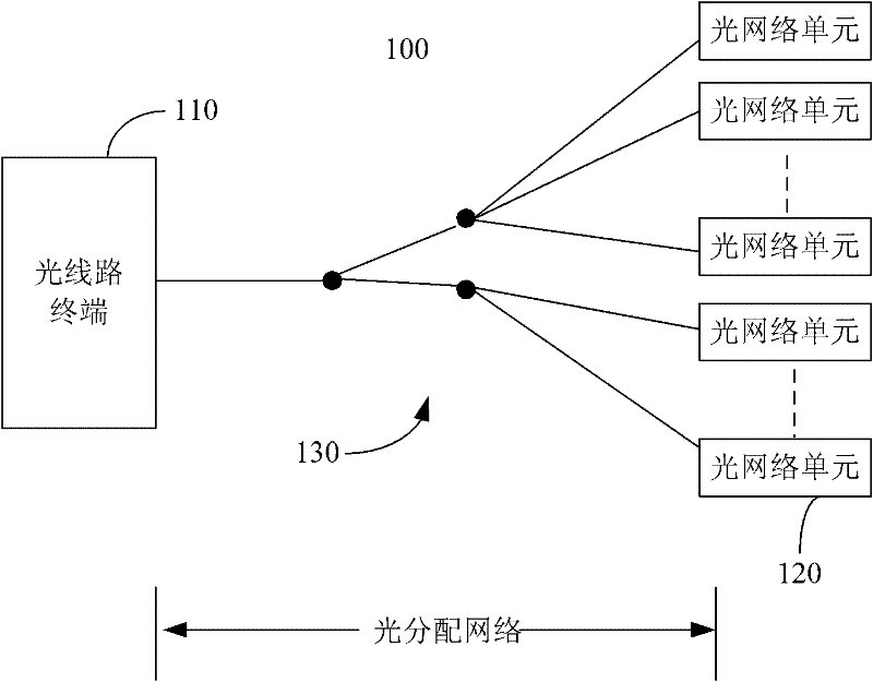
[0019] see figure 1 , which is a schematic structural diagram of a passive optical network system to which the optical power detection solution provided by the embodiment of the present invention is applicable. The passive optical network system 100 includes at least one optical line terminal 110 , a plurality of optical network units 120 and an optical distribution network 130 . The optical line terminal 110 is connected to the plurality of optical network units 120 in a point-to-multipoint manner through the optical distribution network 130 . Wherein, the direction from the OLT 110 to the ONU 120 is defined as the downlink direction, and the direction from the ONU 120 to the OLU 110 is defined as the uplink direction.

[0020] The passive optical network sys...


PUM


Abstract

The embodiment of the invention discloses a device for detecting optical power of a passive optical network (PON). The device comprises a receiving module, a detection module and a controller, wherein the receiving module is used for receiving optical signals sent by an optical network unit (ONU); the detection module comprises a current mirror received signal strength indication (RSSI) detection branch and a logarithmic amplifier RSSI detection branch; the current mirror RSSI detection branch and the logarithmic amplifier RSSI detection branch are respectively coupled with the receiving module and used for carrying out RSSI measurement on the optical signals received by the receiving module in accordance with received RSSI function trigger signals; and the controller is coupled with the detection module and used for outputting the RSSI function trigger signals to the detection module, selectively receiving RSSI measurement results which are output by the RSSI detection branch and correspond to the luminous intensity of the optical signals sent by the ONU according to the selection control signals provided by a selection control signal generating module, and calculating the optical power information of the optical signals in accordance with the RSSI measurement results. The embodiment of the invention also discloses a method for detecting optical power of a PON and a PON system.

Description

technical field [0001] The present invention mainly relates to passive optical network technology, in particular to a method, system and device for detecting optical power of a passive optical network. Background technique [0002] As "optical access copper retreat" has gradually become the mainstream access method of network technology, the application of optical access technology has been vigorously developed. A passive optical network (Passive Optical Network, PON) technology is a point-to-multipoint (Point to Multi Point, P2MP) based optical access technology. The passive optical network system mainly includes an optical line terminal (Optical Line Terminal, OLT) located in the central office, a plurality of optical network units (Optical Network Unit, ONU) located on the user side, and a distribution or multiplexing optical line terminal and optical network Optical distribution network for data signals between units. Wherein, the direction from the OLT to the ONU is d...

Claims


Application Information

Patent Timeline
IPC IPC(8): H04B10/08H04Q11/00H04B10/079H04B10/272
CPCH04B10/272H04B10/07955H04Q11/0067H04B10/07H04Q2011/0083
Inventor 王莹
Owner HUAWEI TECH CO LTD
Why Eureka
Try Eureka