Polycrystalline silicon reducing furnace and operating method thereof

An operation method and technology of reduction furnace, applied in chemical instruments and methods, silicon compounds, inorganic chemistry, etc., can solve problems such as inversion of rods, and achieve the effect of avoiding rod inversion and reducing temperature gradient

Inactive Publication Date: 2011-07-27
TIANJIN UNIV
View PDF5 Cites 7 Cited by
  • Summary
  • Abstract
  • Description
  • Claims
  • Application Information

AI Technical Summary

Problems solved by technology

Combining the above two factors, the polysilicon products produced in the traditional polysilicon reduction furnace and the reduction furnace improved by the predecessors are mostly in the shape of "mushrooms", and the structure with a thin bottom and a thick top can easily lead to the occurrence of "inverted rods"

Method used


Image

  • Polycrystalline silicon reducing furnace and operating method thereof
  • Polycrystalline silicon reducing furnace and operating method thereof
  • Polycrystalline silicon reducing furnace and operating method thereof

Examples


Embodiment Construction

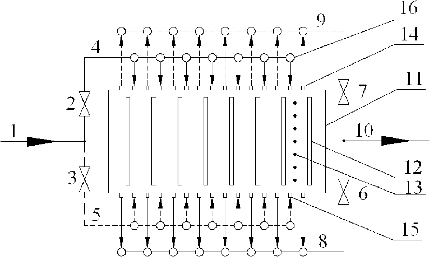
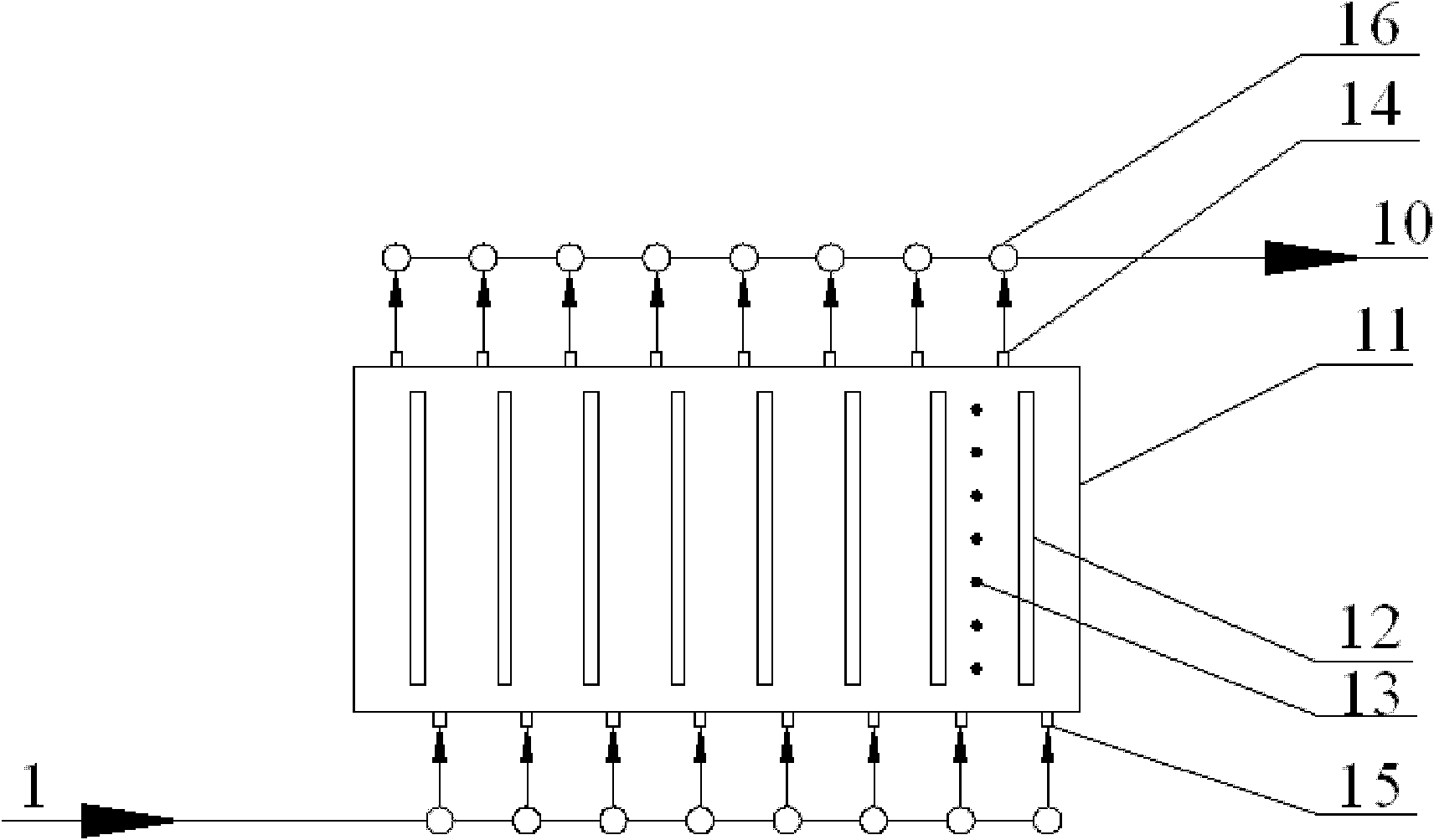
[0015] In order to further illustrate the specific technical characteristics of the polysilicon reduction furnace developed in this patent and the corresponding operating process, we will now describe it in detail in conjunction with the accompanying drawings:

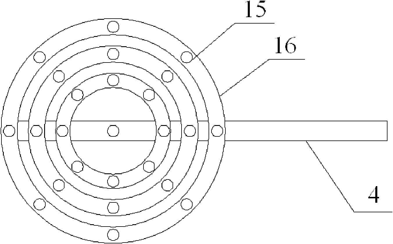
[0016] like figure 1 As shown, the inlet pipes 15 of the polysilicon reduction furnace developed by the present invention are respectively arranged on the top and the bottom of the reduction furnace, and are all of 25 nozzle type structures, such as image 3 As shown, each inlet pipe 15 on the top of the polysilicon reduction furnace is connected to the feed sub-stream 4 of the reduction furnace through the opening on the top of the ring pipe 16, and the raw material 1 first enters into each connected ring through the feed sub-stream 4 or 5 pipes. In the pipe 16, then through each inlet pipe 15, enter the polysilicon reduction furnace 11 to react; the outlet pipe 14 of the polysilicon reduction furnace is respectively...


PUM


Abstract

The invention relates to a polycrystalline silicon reducing furnace and an operating method thereof. Both the top of the reducing furnace and a base are provided with an inlet and an outlet for a material, the inlet and the outlet are of uniformly distributed 25 to 32 pipe orifice type structures, and each inlet or outlet pipe on the polycrystalline silicon reducing furnace in the structure is connected with a corresponding feeding or discharge sub flow through a communicated ring pipe. For the inlet, the raw material enters each communicated ring pipe through a feeding sub flow pipeline, and then enters the polycrystalline silicon reducing furnace through each air inlet pipe to react; and for the outlet, the tail gas is collected into the corresponding communicated ring pipe through each air outlet pipe, finally is converged and flows out of the reducing section through a discharge sub flow pipeline. According to the novel polycrystalline silicon reducing furnace and the operating method for periodically switching the inlet and the outlet of the polycrystalline silicon reducing furnace, obvious temperature gradient in the polycrystalline silicon reducing furnace manufactured by the prior art can be effectively reduced; and 'inverse bar' is avoided, and post treatment of a product is favorable.

Description

technical field [0001] The invention relates to a polysilicon reduction furnace in the technical field of polysilicon production and a corresponding operation method thereof, in particular to a novel reduction furnace capable of realizing fully mixed flow inside the polysilicon reduction furnace and an operation method thereof. Background technique [0002] At present, the main process technology for polysilicon production at home and abroad is the improved Siemens method. The core step of the process technology, the reduction reaction of trichlorosilane, is carried out in a polysilicon reduction furnace: high-purity trichlorosilane and hydrogen are mixed in proportion and then passed into the polysilicon reduction furnace, at a certain temperature (1080 ℃~1150℃) and pressure, a deposition reaction occurs on the energized high-temperature silicon core to form a polysilicon rod-shaped product. Generally speaking, the inlet and outlet of the traditional polysilicon reduction ...

Claims


Application Information

Patent Timeline
Patent Type & Authority Applications(China)
IPC IPC(8): C01B33/035
Inventor 刘春江赵丹李雪段长春袁希钢
Owner TIANJIN UNIV
Why Eureka
Try Eureka