
Time trigger type real-time simulation control system

A technology of control system and real-time simulation, applied in general control system, control/adjustment system, instrument, etc., can solve the problems of inconvenient use and high cost, and achieve the effect of reducing cost

Inactive Publication Date: 2011-07-27
SHANGHAI PAL FIN AUTOMATIC CONTROL TECH
View PDF4 Cites 7 Cited by
  • Summary
  • Abstract
  • Description
  • Claims
  • Application Information

AI Technical Summary

Problems solved by technology

[0006] In view of this, the present invention provides a time-triggered real-time simulation control system to solve the existing dSPACE real-time simulation system that requires multiple different I / O boards and additional driving circuits. Inconvenience

Method used


Image

  • Time trigger type real-time simulation control system
  • Time trigger type real-time simulation control system
  • Time trigger type real-time simulation control system

Examples


Embodiment Construction

[0022] For reference and clarity, technical terms, abbreviations or abbreviations used hereinafter are summarized as follows:

[0023] Matlab: Matrix Laboratory, matrix laboratory;

[0024] TCP / IP: Transmission Control Protocol / Internet Protocol, Transmission Control Protocol / Internet Interconnection Protocol.

[0025] The following will clearly and completely describe the technical solutions in the embodiments of the present invention with reference to the accompanying drawings in the embodiments of the present invention. Obviously, the described embodiments are only some, not all, embodiments of the present invention. Based on the embodiments of the present invention, all other embodiments obtained by persons of ordinary skill in the art without creative efforts fall within the protection scope of the present invention.

[0026] The embodiment of the present invention discloses a time-triggered real-time simulation control system to solve the existing dSPACE real-time simul...


PUM


Abstract

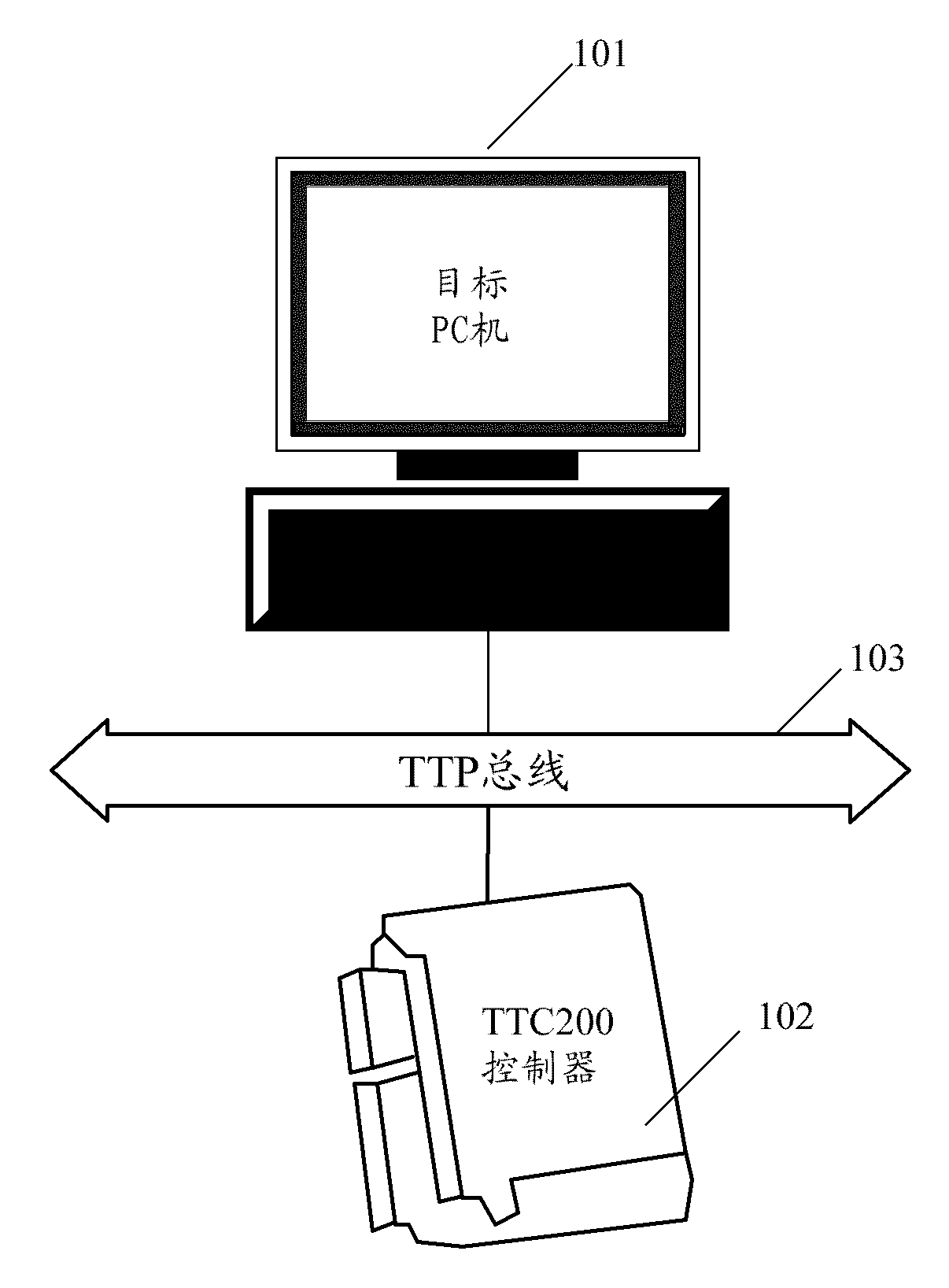
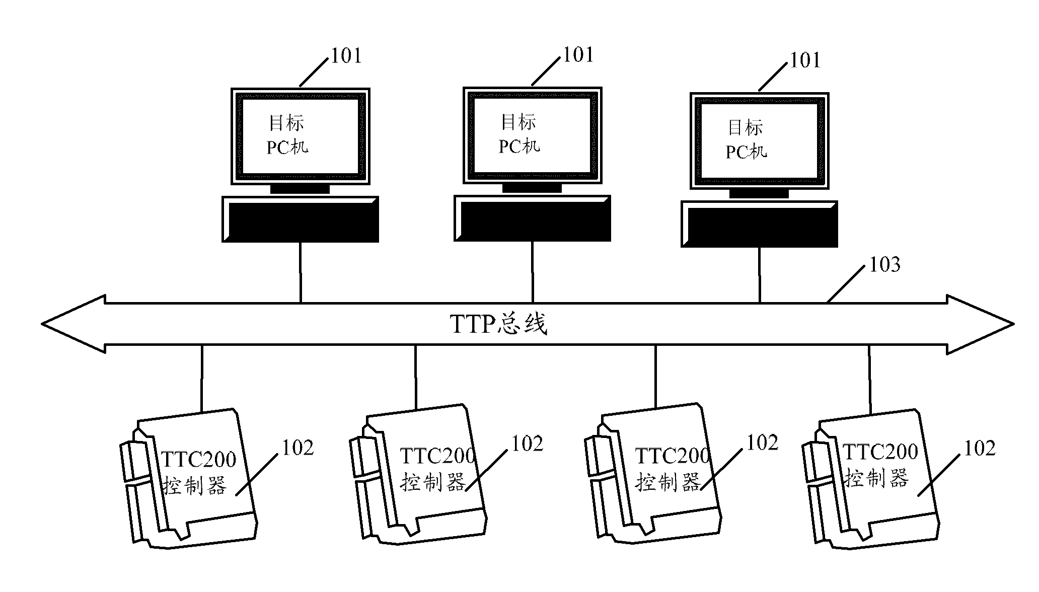
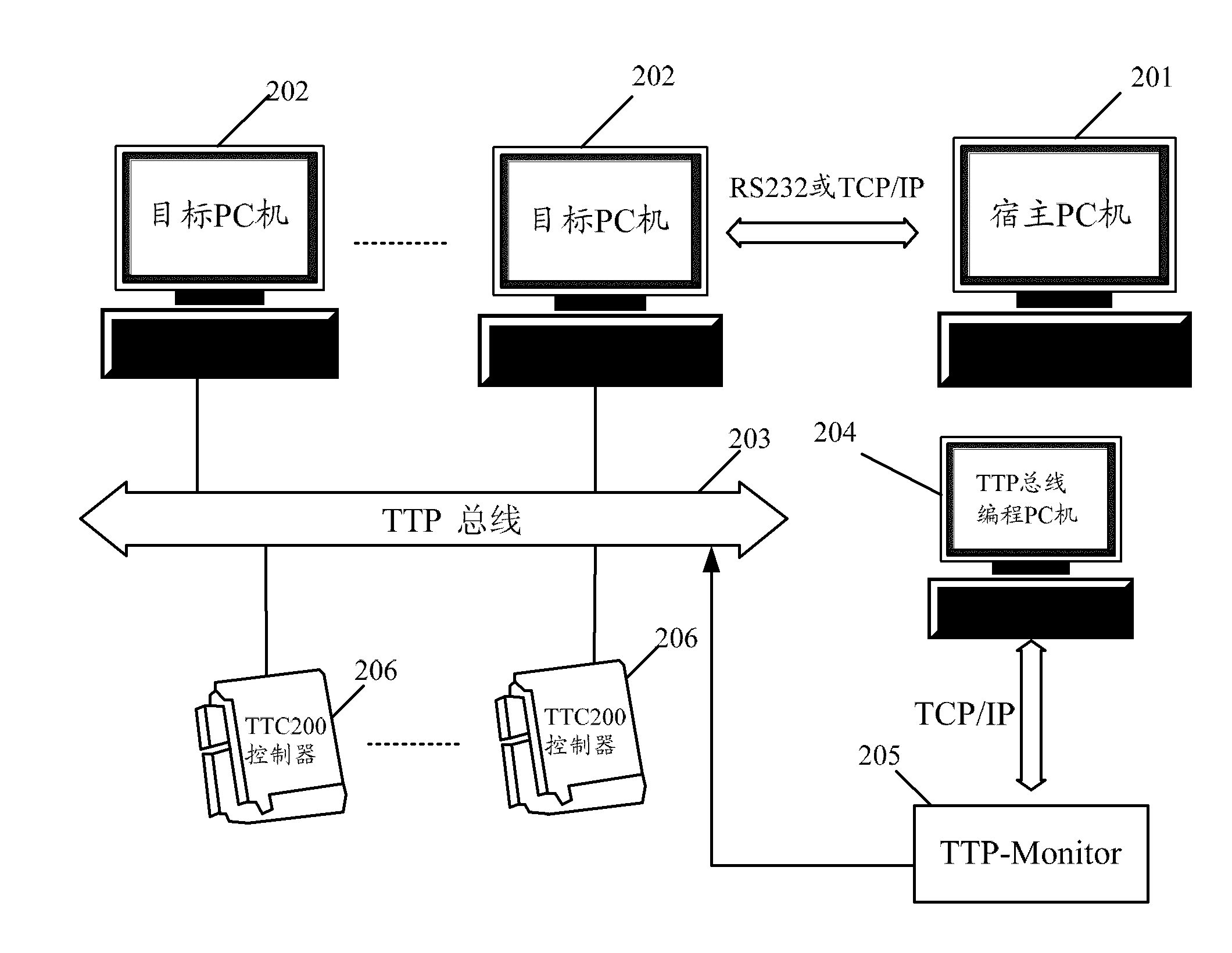
The invention discloses a time trigger type real-time simulation control system which comprises a target PC (personal computer) and TTC200 controllers connected with the target PC through a TTP (Time-Triggered Protocol) bus, wherein the TTC200 controllers exchange data with the target PC through the TTP bus, each TTC200 controller has rich I / O ports, each I / O port is provided with a driving circuit which can output 50-ampere current, and the I / O ports are connected with a control system to drive the control system to act. The time trigger type real-time simulation control system disclosed by the invention adopts the TTC200 controllers, the controllers are provided with the I / O ports, the I / O parts are provided with the driving circuits, and no extra I / O board card and driving circuit is needed, thus the problems of higher cost and inconvenience in use of the traditional dSPACE real-time simulation system, caused by needing a plurality of I / O board cards and additionally providing a driving circuit, are solved.

Description

technical field [0001] The invention relates to the technical field of automatic control, in particular to a time-triggered real-time simulation control system. Background technique [0002] In today's automatic control field, the controlled object is becoming more and more complex, and the control quality is getting higher and higher. The increase in control complexity means that the mechanical parts of the system become more complex, so more complex controllers are required. [0003] However, the design process of complex controllers is also extremely complicated. The existing method is usually: after designing the prototype, then directly manually program the microcontroller or PLC according to the system specification, and manually adjust the controller in the prototype algorithm. At this stage, programmers who are proficient in software are required, and a lot of time is spent on programming, error checking, debugging, and verification. The workload is heavy and the cy...

Claims


Application Information

Patent Timeline
IPC IPC(8): G05B17/02
Inventor 李永刚王小菊谭峙
Owner SHANGHAI PAL FIN AUTOMATIC CONTROL TECH
Learn More