Network recovery method and device

A network recovery and network technology, applied to the selection device, selection device, data exchange network and other directions of the multiplexing system, can solve the problems of IP link congestion, IP link failure, failure of optical layer LSP recovery, etc. The effect of reducing impact and improving connectivity

Active Publication Date: 2011-07-27
HUAWEI TECH CO LTD
View PDF3 Cites 33 Cited by
  • Summary
  • Abstract
  • Description
  • Claims
  • Application Information

AI Technical Summary

Problems solved by technology

[0005] After a network failure occurs, for example, the optical fiber is cut, the optical layer LSP (Label Switched Path, Label Switched Path) will be interrupted, and the corresponding IP link will also be interrupted. These affected optical layer LSPs will initiate a protection switching operation or Re

Method used


Image

  • Network recovery method and device
  • Network recovery method and device
  • Network recovery method and device

Examples


Embodiment 1

[0032] This embodiment provides a network recovery method, such as figure 2 As shown, the method includes:

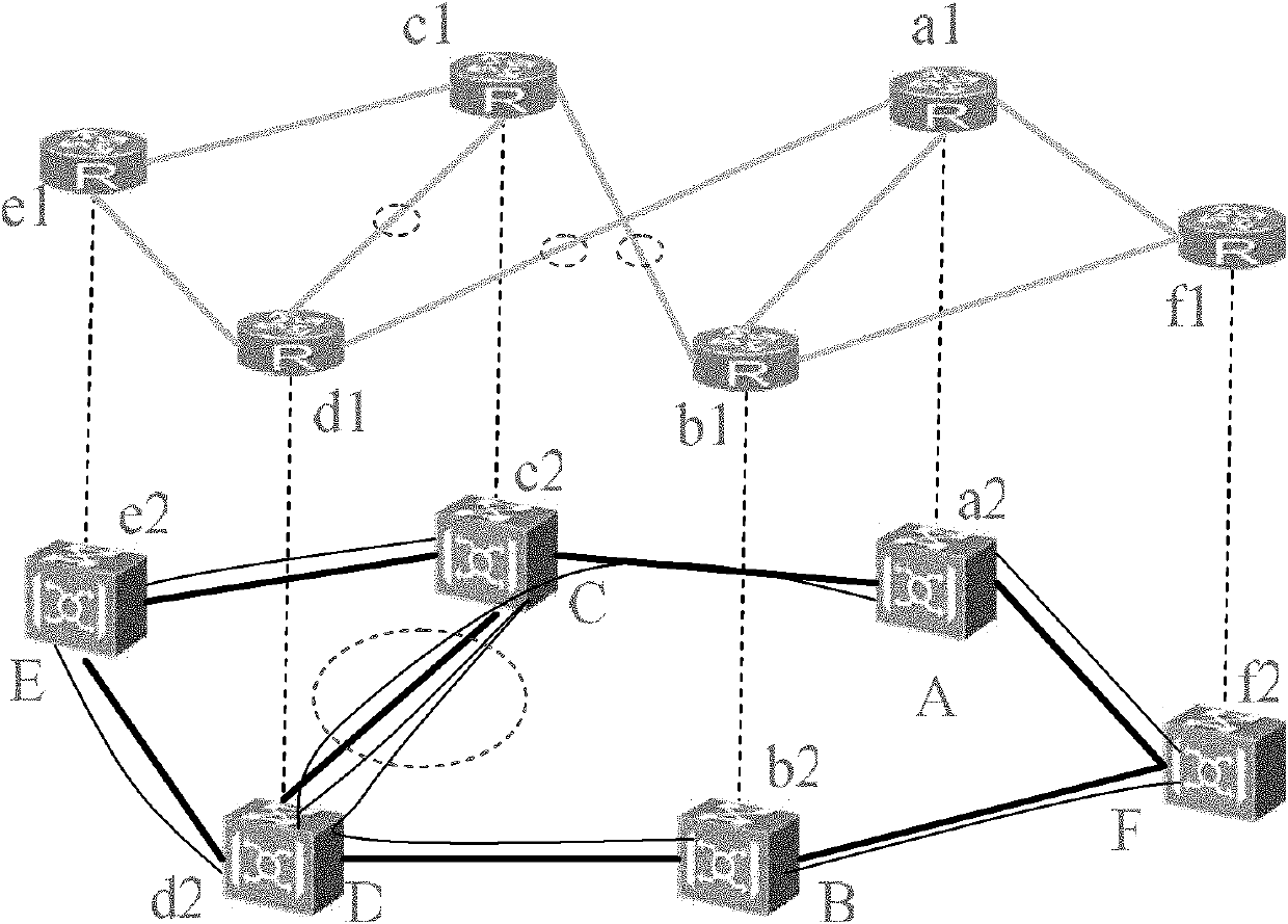
[0033] S10. Obtain the network status and available resources of the network when the optical layer of the network fails.

[0034] The network state may include topology information of the IP layer, connection relationship between various sites, resource usage status of IP layer routers and optical network devices in each site, and the like. Optical layer resources may include optical fibers, wavelengths, bands, and single-board ports on optical network equipment, etc., and IP-layer resources may include single-board ports of IP-layer routers.

[0035] The available resources may include idle resources of the optical layer and the IP layer, and intact resources in the optical layer LSP where a fault occurs and intact resources in the IP link corresponding to the LSP. The idle resources are usually spare resources on the device. For example, there are two optical fibe...

Embodiment 2

[0050] This embodiment provides a network recovery method, such as Figure 5 shown, including the following steps:

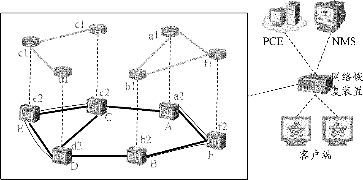
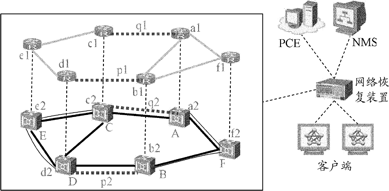
[0051] When the optical layer of the network fails, S101, the network recovery device obtains the network status and available resources of the network.

[0052] In the embodiment of the present invention, the network recovery device may be an IPOCE (IP over Optical Computation Element, IP on an optical computing unit) device, or a PCE (Path Computation Element, path computing unit) integrated with an IPOCE function, or an NMS (Network Management System, network management system) system) or other network elements. The available resources include idle resources of the optical layer and the IP layer, intact resources in the optical layer LSP where a fault occurs, and intact resources in the IP link corresponding to the LSP.

[0053] The network recovery device can determine available resources on the network according to locally recorded network information. I...

Embodiment 3

[0081] This embodiment provides a network recovery device, such as Figure 6 As shown, it includes a first acquisition module 10 , a calculation module 20 , and a notification module 30 .

[0082] The first obtaining module 10 is used to obtain the network status and available resources of the network when the optical layer of the network fails; the available resources may include idle resources of the optical layer and the IP layer, and the faulty optical layer LSP The intact resources of and the intact resources in the IP link corresponding to the LSP.

[0083] If the IP layer of the network also fails, the available resources acquired by the first acquisition module 10 may also include: intact resources in the failed IP link and intact resources in the optical layer LSP corresponding to the IP link.

[0084] The first acquiring module 10 may specifically include:

[0085] The first obtaining unit is configured to determine the available resources on the network according ...


PUM


Abstract

The embodiment of the invention discloses a network recovery method and a device, wherein the network recovery method comprises the steps of: obtaining the network status and available resources of the network after an optical layer of the network fails, wherein the available resources comprise free resources of the optical layer and an IP (internet protocol) layer, intact resources of an LSP of the failed optical layer and intact resources of an IP link corresponding to the LSP; computing the path information of a new optical layer LSP, the corresponding IP link and configuration informationcorresponding to the initial node and tail node of the IP link by utilizing the available resources according to the status of the network; informing the initial node and tail node of the new opticallayer LSP of building an optical layer LSP according to the path information of the new optical optical-layer LSP; and issuing the configuration information to the initial node and tail node correspondingly. The new optical layer LSP and the corresponding IP link can be computed by utilizing the available resources, thus improving the connectivity of the IP and the optical network.

Description

technical field [0001] The present invention relates to network failure recovery technology, in particular to a network recovery method and device. Background technique [0002] The rapid development of optical network technology has brought almost unlimited bandwidth and transparent access capabilities to people. By optimizing and integrating optical networks for IP (Internet Protocol) services, operators have constructed a network that is suitable for future business development needs, including IP layer and optical layer network to meet the growing business needs. [0003] The network comprising the IP layer and the optical layer is a multi-layer network, and the equipment therein can be: SDH (Synchronous Digital Hierarchy, Synchronous Digital System) equipment, SONET (Synchronous Optical Networking, Synchronous Optical Network) equipment, OTN (Optical TransportNetwork , Optical Transport Network) equipment, CWDM (Coarse Wavelength Division Multiplexing, sparse wavelengt...

Claims


Application Information

Patent Timeline
IPC IPC(8): H04L12/24H04B10/08H04L45/24H04L45/28H04L45/50
CPCH04L45/28H04Q11/0062H04J14/0257H04Q2011/0081H04L45/50H04L12/00H04J14/0284H04L45/64H04J14/0258H04L45/22H04L41/0654H04J14/0268
Inventor 刘欣超
Owner HUAWEI TECH CO LTD
Why Eureka
Try Eureka