High-accuracy train positioning system based on radio frequency technology and positioning method thereof

A technology of train positioning and radio frequency technology, which is applied in the high-precision train positioning system and its positioning field, can solve the problems of the GPS receiver having a great influence, unable to fully meet the needs of actual rail train mileage detection, and increasing the system error, so as to improve the performance of the system. The effect of detection accuracy

Inactive Publication Date: 2011-08-03
RAILWAY INFRASTRUCTURE TESTING RES INST CHINA ACAD OF RAILWAY SCI +1
View PDF5 Cites 37 Cited by
  • Summary
  • Abstract
  • Description
  • Claims
  • Application Information

AI Technical Summary

Problems solved by technology

[0005] The disadvantage of this manual mileage setting method is that it increases the workload of the inspectors and makes the inspection task more onerous; the operator may input the mileage incorrectly when correcting, resulting in system mileage errors; sooner or later, different people press the correction key. The difference increases the system error; the detection is restricted by the environment, and the mileage sign cannot be corrected manually in an environment with poor visual distance at night; the train speed is too fast, which may also cause the mileage sign to be unable to be seen manually, resulting in the inability to perform mileage correction fix
[0007] The shortcoming of this kind of photoelectric encoder detection method is: the long-term operation of the train, the wear and tear of the wheel itself will cause the circumference to become smaller, and the distance represented by each pulse will become smaller, resulting in errors in the detection data; when the train brakes and other actions, the wheel It will slip, and the axle will not d

Method used


Image

  • High-accuracy train positioning system based on radio frequency technology and positioning method thereof
  • High-accuracy train positioning system based on radio frequency technology and positioning method thereof
  • High-accuracy train positioning system based on radio frequency technology and positioning method thereof

Examples


Embodiment 1

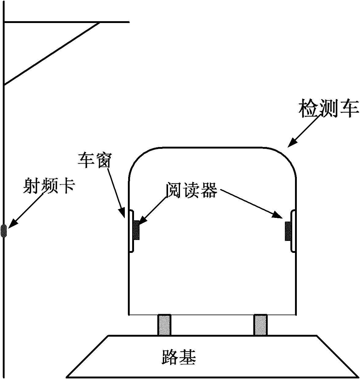
[0081] Such as image 3 As shown, in the high-precision train positioning system based on radio frequency technology in this embodiment, the radio frequency card is installed on the utility pole beside the track. The train positioning system includes two readers, which are respectively installed on both sides of the rail car compartment and correspond to the radio frequency cards. Both readers are connected to the processing computer.

[0082] Here, the reason for setting up two readers is mainly to consider that after the rail car turns its head, the one-side reader cannot meet the needs of continuous detection, so the setting requires the other side of the reader in order to continue detection.

[0083] Preferably, the reader is closely attached to the window of the rail car to enhance the communication signal between the reader and the radio frequency card.

[0084] This embodiment is mainly applicable to the situation that some railcars run at a high speed and have a low...

Embodiment 2

[0086] Such as Figure 4 As shown, in the high-precision train positioning system based on radio frequency technology in this embodiment, the radio frequency card is installed on the milestone beside the track. The train positioning system includes two readers, which are respectively installed on both sides outside the rail car compartment and correspond to the radio frequency cards. Both readers are connected to the processing computer.

Embodiment 3

[0088] Such as Figure 5 As shown, in the high-precision train positioning system based on radio frequency technology in this embodiment, the radio frequency card is installed on the bottom side of the track. The reader of the train positioning system is correspondingly installed on the bottom side of the rail car. The reader is connected to a processing computer.

[0089]This embodiment is mainly applicable to some railcars running at a relatively low speed, or the bottom of the railcar is high, and the distance between the bottom side of the railcar and the track is sufficient to ensure a certain reading range between the radio frequency card and the reader.

[0090] In each of the above embodiments, the reader can be installed inside the compartment, outside the compartment or at the bottom side of the compartment. Depending on the location of the reader, the communication connection between it and the processing computer can also be in different ways, specifically, it ca...


PUM


Abstract

The invention provides a high-accuracy train positioning system based on the radio frequency technology and a positioning method thereof. The high-accuracy train positioning system comprises a radio frequency card arranged on a trackside fixed object and a reader and a processing computer which are arranged on a rail train, wherein the radio frequency card responds to a transmitting signal sent by the reader and returns a reflected signal; the reader receives and processes the reflected signal returned by the radio frequency card to acquire the card number of the radio frequency card and sends the card number to the processing computer; and the processing computer invokes the database of the radio frequency card to identify the positioning information corresponding to the card number of the radio frequency card. The train positioning system and the positioning method carry forward various advantages of the radio frequency technology, overcome the defects of the prior art and can operate accurately and effectively in severe environment. In addition, the invention also provides an error correction scheme for the positioning system, which further increases the detection accuracy of the train positioning system and meets the high requirements of current rail transit development for the detection system.

Description

technical field [0001] The invention relates to the technical field of rail transit facility detection, in particular to a radio frequency technology-based high-precision train positioning system and a positioning method thereof. Background technique [0002] The track inspection vehicle is a large-scale dynamic testing equipment for checking track defects, eliminating hidden dangers of accidents, guiding line maintenance, improving track smoothness, and ensuring driving safety. It is mainly used in rail transit fields such as trains, subways, and trams. The track detection system installed on the track inspection vehicle can dynamically detect the geometric parameters of the track, and the detection data and overruns play a very important role in guiding road maintenance and maintenance in public works sections and ensuring driving safety. The overrun data detected by the track inspection vehicle needs to be marked with mileage, so that the engineering section can accurate...

Claims


Application Information

Patent Timeline
IPC IPC(8): B61L25/02
Inventor 杨爱红王登阳杨超任盛伟魏世斌夏博光谭松
Owner RAILWAY INFRASTRUCTURE TESTING RES INST CHINA ACAD OF RAILWAY SCI
Why Eureka
Try Eureka