Large-scale upper oil tank hydraulic power unit

A hydraulic pump station, top-mounted technology, applied in the direction of fluid pressure actuation device, fluid pressure actuation system components, mechanical equipment, etc., can solve the problems of low installation center of gravity, large vibration amplitude and noise of oil pump and motor, and achieve The effects of reducing load power, occupying less space, and less vibration

Inactive Publication Date: 2011-08-03
KEDA INDUSTRIAL GROUP CO LTD
View PDF8 Cites 7 Cited by
  • Summary
  • Abstract
  • Description
  • Claims
  • Application Information

AI Technical Summary

Problems solved by technology

The side-mounted oil tank is adopted. Since the oil tank is installed side by side with the oil pump, motor and other components, the installation center of gravity of the oil pump, motor and other components is low, and the oil pump and motor work with less vibration and stable operation, but it will increase the floor space of the pump station. greatly increased, affecting the assembly of the host
The lower-mounted oil tank is used, and the oil pump, motor and other components are installed on the upper part of the oil tank. Although this design can reduce the floor space, but because the number of oil pumps and motors in this large pumping station is large and the weight is large, the strength of the oil tank must be It needs to be strengthened to support the weight on it, which will greatly increase the thickness of the tank wall, and at the same time need to increase the assistance of other supports, which not only increases the weight of the pump station, but also wastes manufacturing materials. Moreover, due to the installation of oil pumps, motors and other components The center of gravity is high, and the support of the lower-mounted oil tank is not stable enough. When the pump station is working, the vibration of the oil pump and the motor is relatively large, resulting in loud noise and unstable operation of the pump station.

Method used


Image

  • Large-scale upper oil tank hydraulic power unit
  • Large-scale upper oil tank hydraulic power unit

Examples


Embodiment Construction

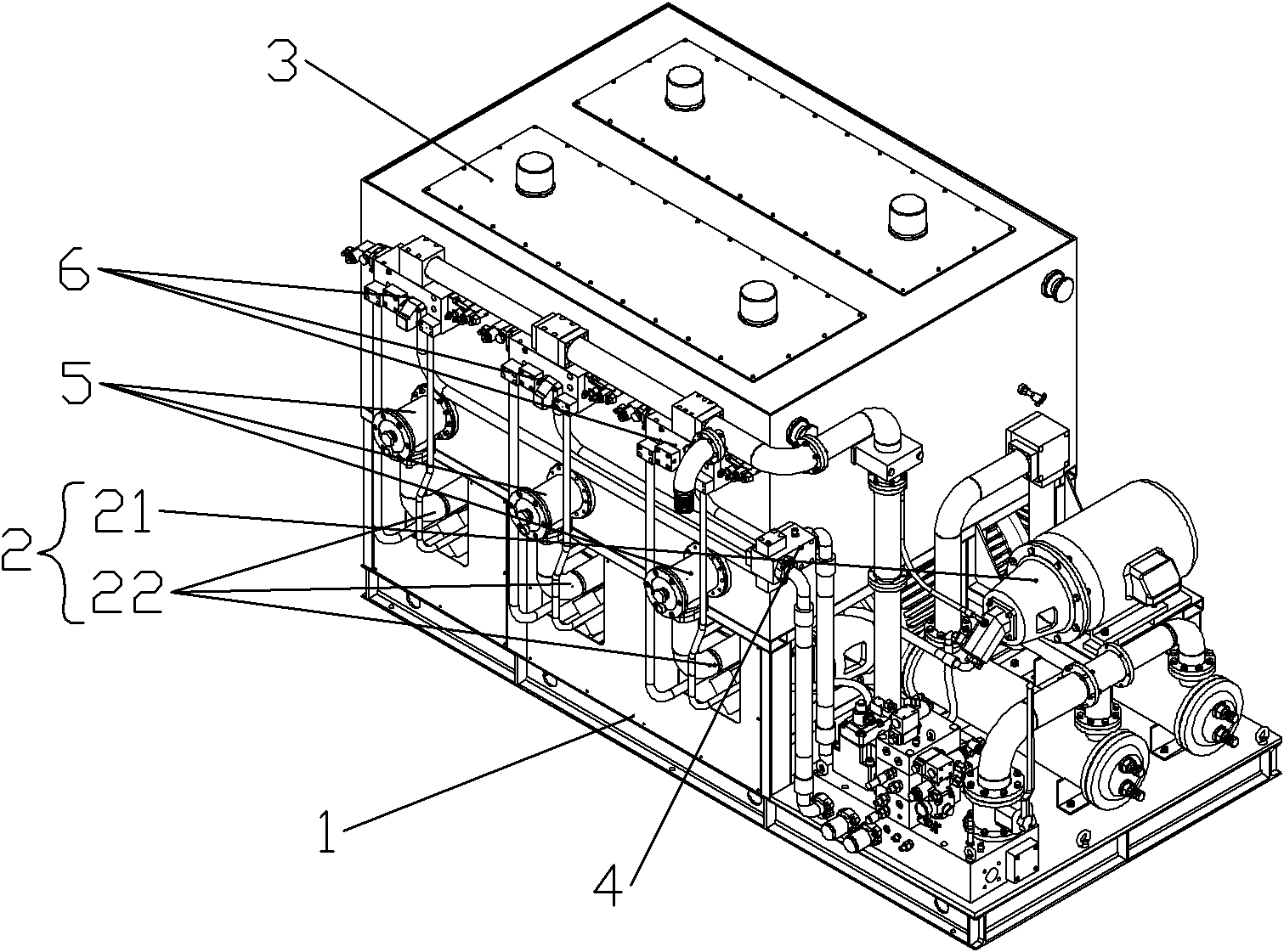
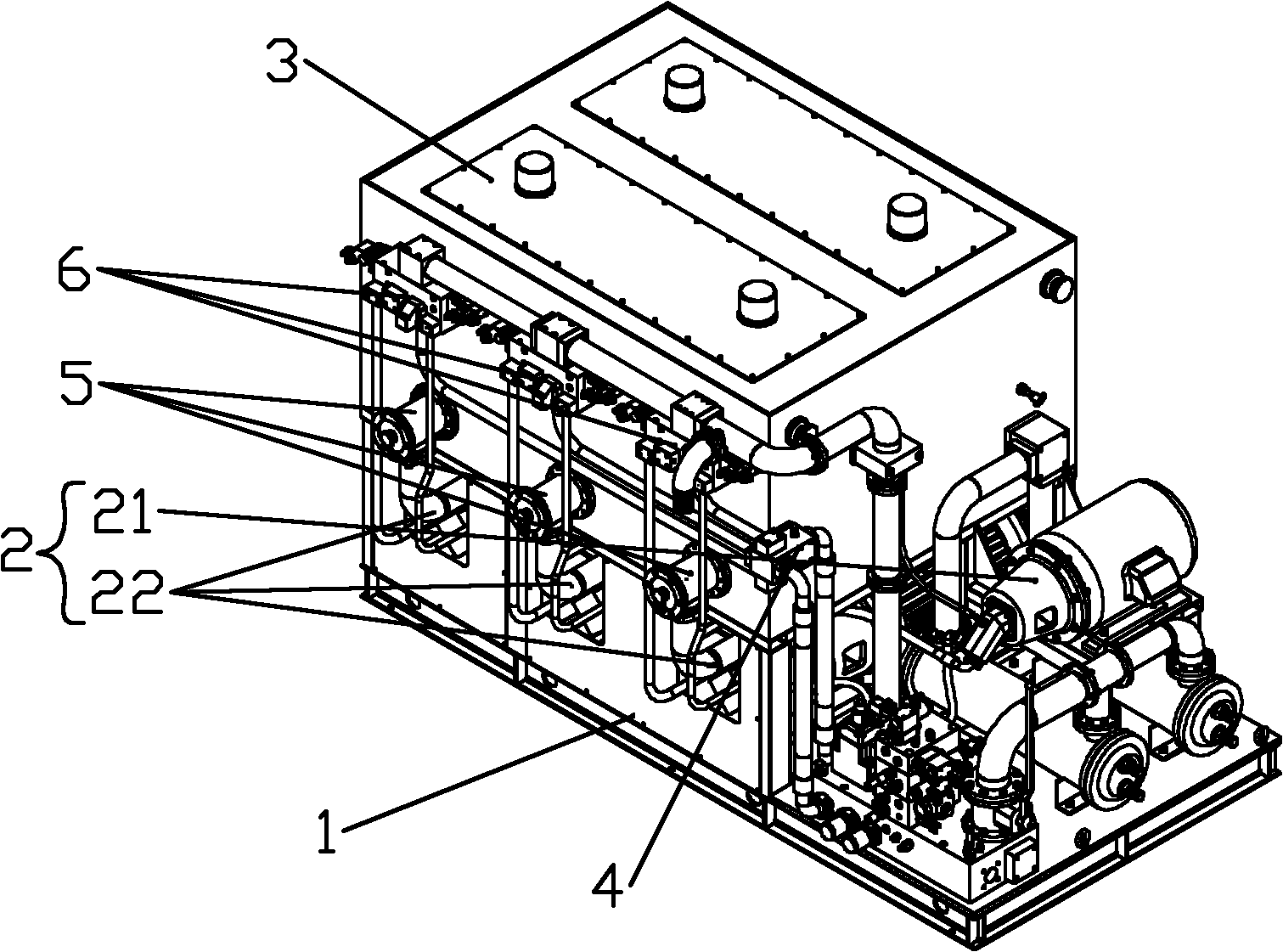
[0014] Such as figure 1 As shown, the large top-mounted oil tank hydraulic pump station described in the present invention is applied to the inner cavity metal extrusion molding machine to provide large flow and adjustable pressure oil for the inner cavity metal extrusion molding machine and provide hydraulic power for each actuator.

[0015] Specifically, the large-scale top-mounted oil tank hydraulic pump station described in the present invention includes a frame 1, an oil pump motor assembly 2 and an oil tank 3. The oil pump motor assembly 2 is installed on the installation platform of the frame 1, and the oil tank 3 passes through The support assembly of the frame 1 is installed above the oil pump motor assembly 2 .

[0016] More specifically, the above-mentioned oil pump motor assembly 2 includes a high-pressure oil pump motor assembly 21 and at least one set of medium-pressure oil pump motor assemblies 22 installed side by side. In an embodiment, the above-mentioned oi...


PUM


Abstract

The invention discloses a large-scale upper oil tank hydraulic power unit. The large-scale upper oil tank hydraulic power unit comprises a machine frame, an oil pump motor assembly and an oil tank; the oil pump motor assembly is arranged on a mounting platform of the machine frame, and the oil tank is arranged above the oil pump motor assembly through a support assembly of the machine frame so as to form an upper oil tank. The design of the upper oil tank is adopted by the hydraulic power unit, and the hydraulic power unit has a compact structure, the advantages of low shaking degree and stability in working of a side oil tank hydraulic power unit and the advantages of small occupied space of a lower oil tank hydraulic power unit; the oil tank is arranged on the upper part to bring convenience to the oil absorption of the oil pump; and due to the action of gravity, under the condition of not adding compressed air on the oil tank, the oil pump can absorb oil easily, and the load power of the oil pump can be reduced.

Description

technical field [0001] The invention relates to a hydraulic pump station, in particular to a large-scale hydraulic pump station with an overhead oil tank. Background technique [0002] In the inner cavity metal extrusion molding machine, due to the large number of actuators, the pressure oil flow provided by the hydraulic pump station is relatively large. Therefore, the capacity of the oil tank is relatively large, resulting in a relatively large volume of the oil tank. There are two ways to place the oil tank in the existing hydraulic pump station: one is to use a side-mounted oil tank, and the other is to use a lower-mounted oil tank. The side-mounted oil tank is adopted. Since the oil tank is installed side by side with the oil pump, motor and other components, the installation center of gravity of the oil pump, motor and other components is low, and the oil pump and motor work with less vibration and stable operation, but it will increase the floor space of the pump stat...

Claims


Application Information

Patent Timeline
Patent Type & Authority Applications(China)
IPC IPC(8): F15B21/00
Inventor 陈伟俊何浩波张昭政
Owner KEDA INDUSTRIAL GROUP CO LTD
Why Eureka
Try Eureka