Electro-spray ion generator

An electrospray ion and generator technology, which is applied in the field of analytical instruments, can solve the problem that the ion transmission efficiency is not significantly improved, and achieve the effects of stable ion emission and high ion transmission efficiency.

Active Publication Date: 2011-08-03
ZHEJIANG HAOCHUANG BIOTECH
View PDF7 Cites 14 Cited by
  • Summary
  • Abstract
  • Description
  • Claims
  • Application Information

AI Technical Summary

Problems solved by technology

However, all inventions place the emission needle tip of the electrospray ion source in the atmosphere, and the ion flow is closely related to the liquid flow rate, and it is imp...

Method used


Image

  • Electro-spray ion generator
  • Electro-spray ion generator
  • Electro-spray ion generator

Examples


Embodiment 1

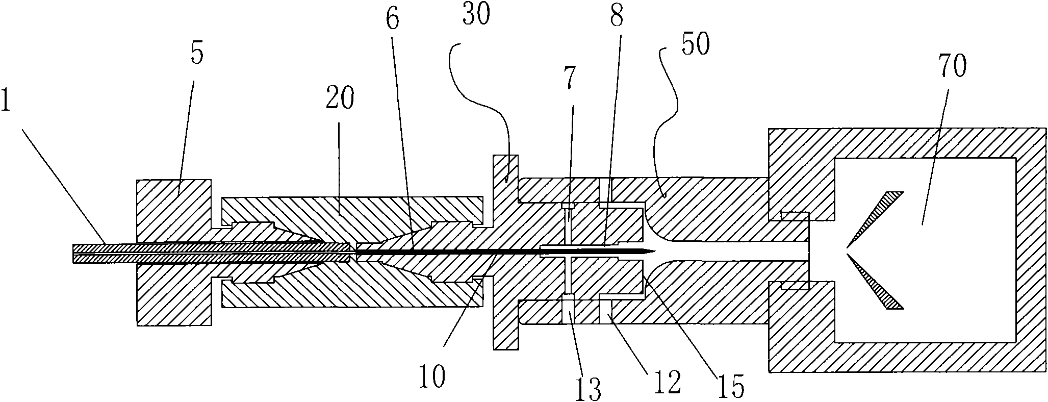
[0039] according to figure 1 , figure 2 , Figure 4 , Figure 5As shown in the structure, an electrospray ion generator is made, which includes a hollow capillary emitting needle 10, a high-voltage electrical connector 20, a hollow capillary emitting needle support 30, and one end of the fixing block 5 is located at the front section of the high-voltage electrical connector 20 cavity. And there is a through hole in the middle of the fixed block 5; the liquid chromatography connecting pipe 1 passes through the through hole in the fixed block 5, and is fixed in the high-voltage electrical connector 20, and the outer wall of the liquid chromatography connecting pipe 1 and the fixed block 5 The inner wall of the through hole is closely matched; the vacuum introduction capillary 50 and the high-voltage electrical connector 20 are matched and connected through the hollow capillary emitting needle bracket 30, and one end of the hollow capillary emitting needle bracket 30 is embedd...

Embodiment 2

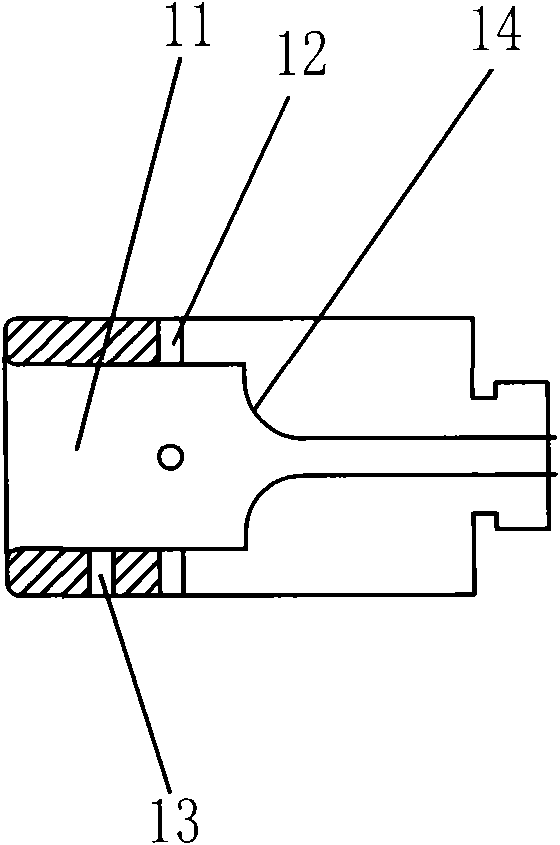
[0048] Adopt the same structure as embodiment 1, have the auxiliary hole 12 to the side of the vacuum introduction capillary 50 wherein, the auxiliary hole 12 is connected with the cavity 11; There are 4 auxiliary holes 12 on the side of the vacuum introduction capillary 50, the auxiliary hole 12 The inner gas is nitrogen; the tip of the hollow capillary emitting needle 10 exceeds the end face 15 of the hollow capillary emitting needle support 30 to be 2 millimeters; the hollow capillary emitting needle 10 is a hollow glass capillary; the vacuum leading capillary 50 is a metal material, and then the hollow capillary The emission needle 10, the vacuum introduction capillary 50, the liquid chromatography connection tube 1, the vacuum introduction capillary 50, the high voltage electrical connector 20, and the hollow capillary emission needle support 30 are on the same axis; the rear end cavity of the hollow capillary emission needle support 30 8 diameters are 1.3 times of the dia...

Embodiment 3

[0050] Adopt the same structure as embodiment 1, have the auxiliary hole 12 to the side of the vacuum introduction capillary 50 wherein, the auxiliary hole 12 is connected with the cavity 11; There are 8 auxiliary holes 12 on the side of the vacuum introduction capillary 50, the auxiliary hole 12 The internal gas is air; the tip of the hollow capillary emitting needle 10 exceeds the end face 15 of the hollow capillary emitting needle support 30 by 5 millimeters; the hollow capillary emitting needle 10 is a hollow metal capillary; the vacuum introduction capillary 50 is made of ceramic material, and then Put the hollow capillary launch needle 10, the vacuum introduction capillary 50, the liquid chromatography connection tube 1, the vacuum introduction capillary 50, the high voltage electrical connector 20, and the hollow capillary launch needle support 30 on the same axis; The diameter of the end cavity 8 is 1.4 times of the diameter of the hollow capillary emission needle 10; t...


PUM


Abstract

The invention discloses the field of an analytical instrument, in particular to an instrument for ion generation of medical micromolecules and biological macromolecules. The instrument is provided with a hollow capillary emission needle and a launch emission support. The emission needle support forms a laminar flow gas flowing forwards around the emission needle to eliminate the capillary reverseflow effect of liquid flowing out from the hollow capillary emission needle outside a capillary, so that the liquid flows forwards. An inlet infused in the capillary in a vacuum mode I specially designed into an arc-shaped mechanism, so the speed of airflow at some position at any direction is zero, the position is just the outlet of the hollow capillary emission needle, therefore the stability of a Taylor cone of the top end of the point of the emission needle is ensured in the large flow range, and finally a stable ion flow is obtained. The instrument has the advantages of stable ion emission, high ion transmission efficiency and the like and can be widely applied to occasions of ion source preparation.

Description

technical field [0001] The invention relates to the field of analytical instruments, in particular to an instrument used for generating ions of medical small molecules and biological macromolecules. technical background [0002] Since the mid-1980s, John B. Fenn, one of the 2002 Nobel Prize winners in chemistry, applied the electrospray ion source to the mass spectrometry analysis of macromolecules. More than 20 years have passed, and the electrospray ion source mechanism still stays in two modes. : Ion Evaporation Model (IEM) ion evaporation, and Charged Residue Model (CRM) charge residual mechanism. The basic structure of the electrospray ion source is not essentially different from that of the 1990s. [0003] The basic structure of the electrospray ion source is to fill the middle of a hollow metal or glass capillary with liquid, facing the ion entrance of the mass spectrometer, apply positive or negative high voltage to the liquid, and form positive and negative ions in...

Claims


Application Information

Patent Timeline
IPC IPC(8): H01J49/16G01N30/72
Inventor 朱一心吕婷婷
Owner ZHEJIANG HAOCHUANG BIOTECH
Why Eureka
Try Eureka