Antenna manufacturing method

A manufacturing method and antenna technology, applied in the field of electronics, can solve the problems of reduced antenna performance, low production efficiency and high cost, and achieve the effects of good product adaptability, high production efficiency and good bonding force

Inactive Publication Date: 2014-04-02
SHENZHEN SUNWAY COMM
View PDF7 Cites 3 Cited by
  • Summary
  • Abstract
  • Description
  • Claims
  • Application Information

AI Technical Summary

Problems solved by technology

[0004] First, two sets of molds need to be opened, one set of antenna bracket molds and one set of metal shrapnel molds, the cost is relatively high;
[0005] Second, the metal shrapnel is bent. Since the metal shrapnel needs to be unfolded, when it encounters a part with a special-shaped structure, it is difficult to achieve the bonding between the antenna and the special-shaped part through the bending process, and these must be discarded. Special-shaped parts, thereby reducing the radiator area of ​​the metal shrapnel and reducing the performance of the antenna;
[0006] Third, the metal shrapnel and the bracket need to be assembled, and the assembly process is affected by the operator, not only the production efficiency is low, but also the product consistency is not good
[0008] First, you need to open at least two sets of molds, one set of antenna bracket molds and one set of flexible circuit board shape molds; if there are holes on the flexible circuit board, you need to open a set of punching molds; The production and assembly are easy to operate, and a set of hand-tearing molds and a set of centrifugal paper breaking line molds are required, so the cost is relatively high;
[0009] Second, when the flexible circuit board encounters parts with special-shaped structures, since the flexible circuit board needs to be unfolded and cannot be realized by bending and bonding, these special-shaped parts must be discarded, thereby reducing the radiation of the flexible circuit board body area, reducing antenna performance;
[0010] Third, the flexible circuit board is generally connected to the bracket by pasting, and the structure is not reliable. If the flexible circuit board is warped or shifted, the performance of the antenna will be greatly reduced;
[0011] Fourth, the flexible circuit board and the bracket need to be assembled, and the assembly process is affected by the operator, not only the production efficiency is low, but also the product consistency is not good
[0014] First, the electroplating method uses a two-color mold for injection molding, and requires two injection moldings, the process is complex, time-consuming and laborious;
[0015] Second, due to the two injections, the precision of the injection molding machine and the mold are very high, and the production cost and mold cost are significantly increased;
[0016] Thirdly, each time the antenna is debugged and changed, the project is large, and two sets of molds need to be changed every time the debugging line is changed, resulting in a high cost of making samples

Method used


Image

  • Antenna manufacturing method
  • Antenna manufacturing method
  • Antenna manufacturing method

Examples


Embodiment Construction

[0034] In order to describe the technical content, structural features, achieved goals and effects of the present invention in detail, the following will be described in detail in conjunction with the embodiments and accompanying drawings.

[0035] The antenna manufacturing method of the present invention is abbreviated as PLP, and its full name in English is painting, Laser cutting, Plating.

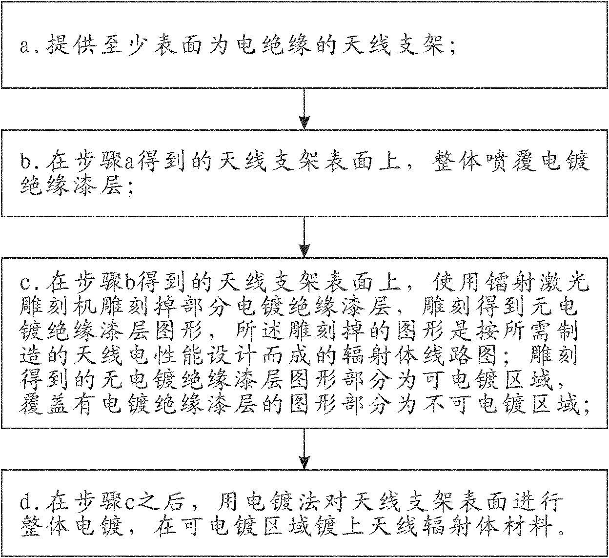
[0036] see figure 1 , the antenna manufacturing method of the present invention, comprises the following steps:

[0037] a. Provide an antenna support that is electrically insulating at least on its surface;

[0038] b. On the electrically insulating surface of the antenna bracket obtained in step a, the overall spray plating insulating varnish layer;

[0039] c. On the surface of the antenna bracket obtained in step b, use a laser engraving machine to engrave part of the electroplating insulating paint layer, and engrave to obtain an electroless plating insulating paint layer pattern...


PUM


Abstract

The invention discloses an antenna manufacturing method, which comprises the following steps of: a, providing an antenna bracket of which at least the surface is electrically isolated; b, spraying an electroplating insulated paint layer on the whole electrically-isolated surface of the antenna bracket obtained in the step a; c, using a laser engraving machine to carve out part of the electroplating insulated paint layer on the surface of the antenna bracket obtained in the step b, and carving to obtain a pattern without an electroplating insulated paint layer; the carved pattern is a radiation body circuit diagram designed according to the electrical property of the antenna needing to be manufactured; part of the carved pattern without the electroplating insulated paint layer is an area capable of being electroplated, and the area covered with the electroplating insulated paint layer is an area which can not be electroplated; and d, after the step c, electroplating the whole surface of the antenna bracket with an electroplating method, and plating an antenna radiation body material on the area capable of being electroplated. The antenna manufacturing method has simple manufacturing process and does not need assembly, the bonding force of a radiation body and a bracket body is good, the consistency of the antenna property is good, the molding speed is high, and the production efficiency is high.

Description

technical field [0001] The invention relates to the field of electronic technology, in particular to an antenna manufacturing method. Background technique [0002] Mobile phone antenna is a very important part of mobile phone parts, which directly determines the quality of mobile phone call performance. There are two conventional mobile phone antenna structures, the first one is composed of a plastic antenna bracket and a metal shrapnel assembled together through a hot-melt column, and the second is composed of a plastic antenna bracket and a flexible circuit board bonded together by glue . [0003] Metal shrapnel antennas have the following disadvantages: [0004] First, two sets of molds need to be opened, one set of antenna bracket molds and one set of metal shrapnel molds, the cost is relatively high; [0005] Second, the metal shrapnel is bent. Since the metal shrapnel needs to be unfolded, when it encounters a part with a special-shaped structure, it is difficult to...

Claims


Application Information

Patent Timeline
Patent Type & Authority Patents(China)
IPC IPC(8): H01Q1/38
Inventor 朱杰贺森林
Owner SHENZHEN SUNWAY COMM
Why Eureka
Try Eureka