Piezoelectric microfluidic mixer

A technology of microfluidics and mixers, which is applied in the direction of fluid mixers, mixers, fluid velocity measurement, etc., can solve the problems of prolonged mixing time, poor mixing effect, small Reynolds number, etc., achieve good mixing effect and promote mixing , fast response effect

Inactive Publication Date: 2011-08-10
JIANGSU UNIV
View PDF4 Cites 26 Cited by
  • Summary
  • Abstract
  • Description
  • Claims
  • Application Information

AI Technical Summary

Problems solved by technology

At present, the size of the microchannel in the microfluidic mixer is in the range of tens to hundreds of microns. The Reynolds number of the liquid in the microchannel is so small that there is no eddy current, and the mixing between liquids is mainly based on molecular diffusion, making Compared with the macro situation, the mixing time is greatly prolonged and the mixing effect becomes worse. Therefore, special methods must be adopted to increase the micro-contact area between liquids or enhance convection to improve mixing efficiency.

Method used


Image

  • Piezoelectric microfluidic mixer
  • Piezoelectric microfluidic mixer
  • Piezoelectric microfluidic mixer

Examples


Embodiment Construction

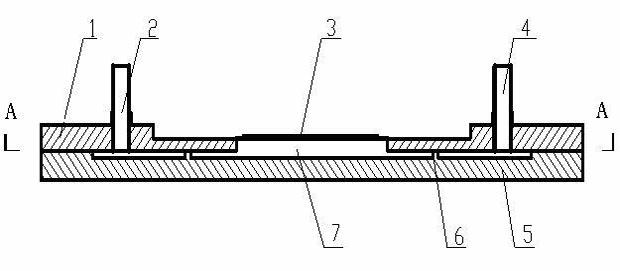
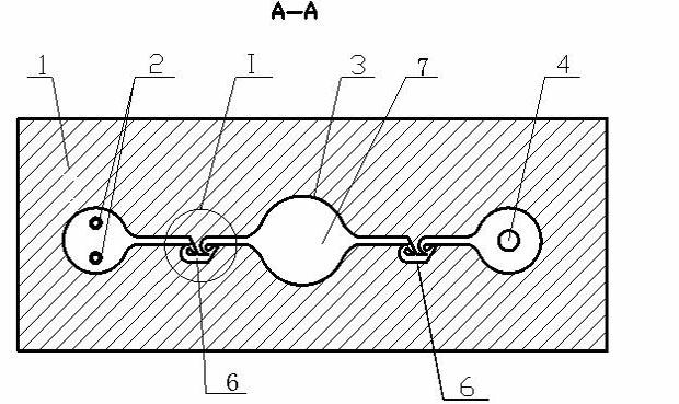
[0015] Such as Figure 1-2 , the present invention has a pump body 5, the material of the pump body 5 is a silicon chip, the upper part of the pump body 5 is an upper substrate 1, the materials of the pump body 5 and the upper substrate 1 are glass, and the pump body 5 and the upper substrate 1 are bonded by an anode Combining technology together. On the upper substrate 1, two pump inlets 2, one pump outlet 4 and one pump chamber 7 are processed by laser, wherein the pump chamber 7 is located in the middle of the upper substrate 1, and the pump inlet 2 and pump outlet 4 are respectively located on the two sides of the pump chamber 7. side. The radius of the pump cavity 7 is 1500 Å, and the height of the pump cavity 7 is 130 Å. The inlet cavity and the outlet cavity are processed on the pump body 5 by dry etching process, the inlet cavity communicates with the pump inlet 2 on the upper substrate 1 , and the outlet cavity communicates with the pump outlet 4 on the upper substr...


PUM


Abstract

The invention discloses a piezoelectric microfluidic mixer, which is characterized in that: a deformation mixing pipe is communicated between two pump inlets and a pump cavity, and between a pump outlet and the pump cavity respectively, the deformation part of the deformation mixing pipe is composed of seven pipelines in a communicating way, a third pipeline is parallel to a first pipeline and the third pipeline, a semicircular second pipeline and a conical seventh pipeline are connected in parallel between the right end of the first pipeline and the left end of the third pipeline, the large end of the conical seventh pipeline is connected with the first pipeline and the second pipeline while the small end of the conical seventh pipeline is connected to the side part of the third pipeline; a semicircular sixth pipeline and a conical fourth pipeline are connected in parallel between the left end of a fifth pipeline and the right end of a third pipeline, and the large end of the conicalfourth pipeline is connected with the right end of the third pipeline and the sixth pipeline respectively while the small end of the conical fourth pipeline is connected to the sidewall of the fifth pipeline; two fluids to be mixed flow, through the inlets, into the deformation mixing pipe at the left side for preliminary mixing, then enter the pump cavity for sufficient mixing and finally flow out of the outlet through the mixing pipe at the right side, so satisfactory effect can be achieved by sufficiently mixing the fluids three times, and simultaneously, pumping and mixing are realized.

Description

technical field [0001] The invention relates to the technical field of micro-fluid pumps in micro-fluid machines, in particular to a piezoelectric micro-fluid mixer capable of mixing a small amount of liquid and controlling the direction of fluid. Background technique [0002] The microfluidic mixer is composed of microfluidic quantifiers, micropumps, microvalves, and microchannels. It is used to fully mix various reagents before biochemical reactions and is an important part of microfluidic chips. Compared with the macro-sized mixing device, the size of the microfluidic mixer is reduced, which greatly reduces the energy consumption and the amount of samples and reagents in the flow system, and has a fast response speed and high accuracy. Therefore, it is widely used in chemical analysis, biological and chemical sensing. , Molecular separation, nucleic acid sequencing and analysis, environmental monitoring and other fields have broad application prospects. [0003] Accordin...

Claims


Application Information

Patent Timeline
Patent Type & Authority Applications(China)
IPC IPC(8): B01F5/00B01F5/12B01L3/00B81B1/00B01F25/60
Inventor 何秀华李富禚洪彩
Owner JIANGSU UNIV
Why Eureka
Try Eureka