Metal ring machining device and using method thereof
What is Al technical title?
Al technical title is built by PatSnap Al team. It summarizes the technical point description of the patent document.
A processing device and metal ring technology, applied in wire processing, other household appliances, applications, etc., can solve the problems of complex power mechanism and control mechanism, inability to realize multi-diameter production, and high production cost, and achieve simple mechanical structure and control mechanism. , The effect of low processing and assembly cost and high production efficiency
Inactive Publication Date: 2011-08-10
ZHEJIANG UNIV
View PDF5 Cites 15 Cited by
Summary
Abstract
Description
Claims
Application Information
AI Technical Summary
This helps you quickly interpret patents by identifying the three key elements:
Problems solved by technology
Method used
Benefits of technology
Problems solved by technology
[0003] The existing automatic processing equipment for metal processing parts is divided into two types. One is a fully automatic wire bending hoop machine tool, which includes a traction and feeding mechanism, a straightening mechanism, a bending mechanism and a shearing mechanism, which can form a variety of curved shapes of metal Processing parts, but the power mechanism and control mechanism of this kind of mechanism are complicated, and the maintenance cost is high. For the simple ring forming process, the production cost is relatively high; the other is a simple mechanical ring forming device. The roller forms a certain diameter annular metal ring, which can be cut automatically. Although the mechanical structure and control structure are simple, it cannot realize flexible multi-diameter production.
Method used
Image
Click on the blue label to locate the original text in one second.
Reading with bidirectional positioning of images and text.
Examples
Embodiment Construction
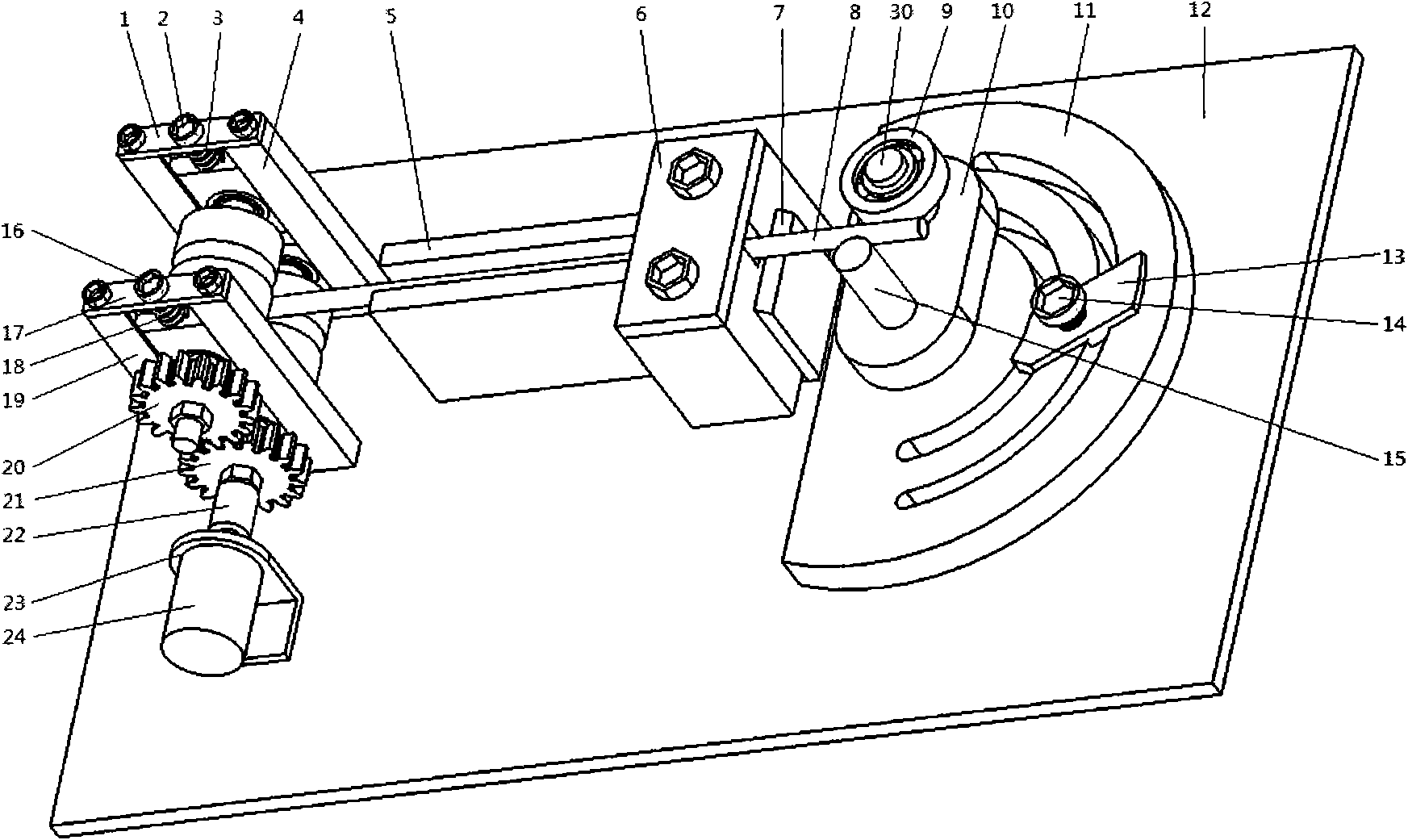
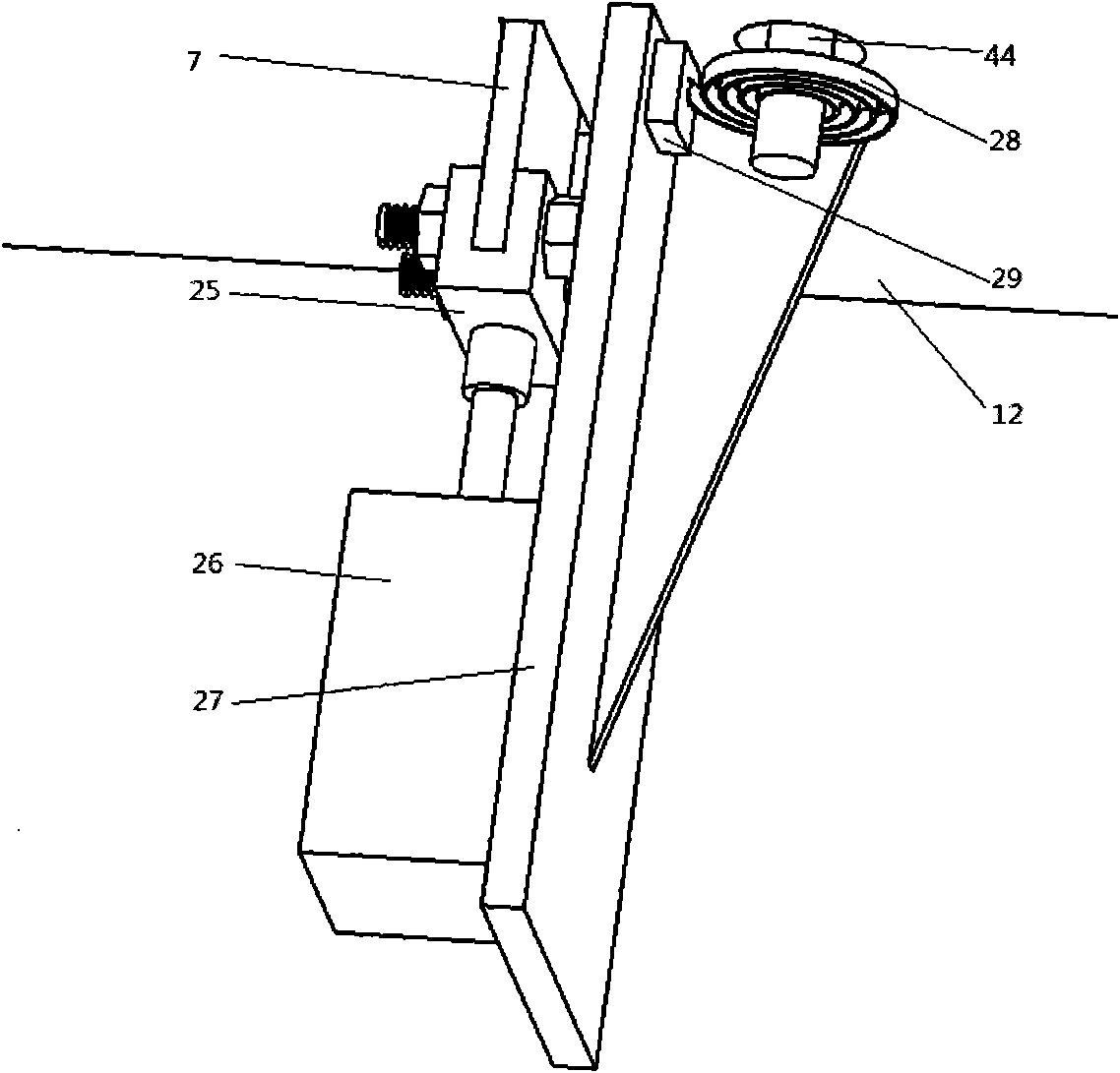
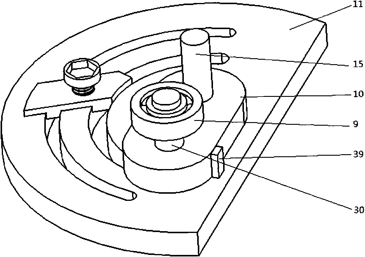
[0024] Such as Figure 1~4 As shown, the eyelet processing device includes a first pressing plate 1, a first adjusting bolt 2, a first pressing bolt 3, a first U-shaped guide rail 4, a feeding guide rail 5, a fixing plate 6, a cutter 7, and a wire to be processed 8 , bending roller 9, rotating block 10, compass 11, workbench 12, pointer 13, pointer fixing screw 14, fixing roller 15, second adjusting bolt 16, second pressing plate 17, second pressing spring 18, second U-shaped guide rail 19, driven gear 20, driving gear 21, coupling 22, motor fixing frame 23, motor 24, cutter fixing frame 25, cylinder 26, cylinder fixing frame 27, reset leaf spring 28, leaf spring fixing block 29. Copper sleeve 30, first bearing fixed block 31, first roller shaft 32, first roller wheel 33, second bearing fixed block 34, second roller shaft 35, second roller wheel 36, third bearing fixed block 37 , the fourth bearing fixed block 38, the limit block 39, the first bearing 40, the second bearing 4...
PUM
Abstract
The invention discloses a metal ring machining device and a using method thereof. The metal ring machining device comprises a first pressing plate, a first adjusting bolt, a first hold-down bolt, a first U-shaped guide rail, a feeding guide rail, a fixed plate, a cutter, a metal wire to be machined, a bending roll wheel, a rotating block, a compass, a working platform, a pointer, a pointer fastening screw, a permanent roll wheel, a second adjusting bolt, a second pressing plate, a second hold-down spring, a second U-shaped guide rail, a driven gear, a driving gear and other parts. When the metal ring machining device is used, a corresponding radius numerical value is marked on the compass, and various annular metal rings or arc-shaped metal rings with different diameters can be automatically formed by only changing the position of the pointer, therefore, the metal ring machining device is more intuitive and feasible in use and operation during production. The metal ring machining device has the advantages of simple mechanical structure and control mechanism, high production efficiency and low working intensity of operators, ensures that automatic control and mechanical production can be realized easily, and meets the requirement for common production, and the product has a certain precision. The metal ring machine device has the advantages of simple structure, convenience for maintenance and low maintenance cost.
Description
technical field [0001] The invention relates to a metal ring processing device and a using method thereof. Background technique [0002] Due to the rapid development of the construction industry, automatic processing devices for metal rings came into being. [0003] The existing automatic processing equipment for metal processing parts is divided into two types. One is a fully automatic wire bending hoop machine tool, which includes a traction and feeding mechanism, a straightening mechanism, a bending mechanism and a shearing mechanism, which can form a variety of curved shapes of metal Processing parts, but the power mechanism and control mechanism of this kind of mechanism are complicated, and the maintenance cost is high. For the simple ring forming process, the production cost is relatively high; the other is a simple mechanical ring forming device, which is passed around a certain diameter The rollers of the machine form an annular metal ring with a certain diameter, ...
Claims
Application Information
Patent Timeline
Application Date:The date an application was filed.
Publication Date:The date a patent or application was officially published.
First Publication Date:The earliest publication date of a patent with the same application number.
Issue Date:Publication date of the patent grant document.
PCT Entry Date:The Entry date of PCT National Phase.
Estimated Expiry Date:The statutory expiry date of a patent right according to the Patent Law, and it is the longest term of protection that the patent right can achieve without the termination of the patent right due to other reasons(Term extension factor has been taken into account ).
Invalid Date:Actual expiry date is based on effective date or publication date of legal transaction data of invalid patent.