Bevel gear shaft tooth surface pitch cone locating tool

A technology for positioning tooling and axles, which is applied in the direction of gear teeth manufacturing devices, belts/chains/gears, gear teeth, etc., can solve problems such as shock vibration, low coaxiality accuracy, noise, etc., to prevent the ring gear from beating and improve The effect of product accuracy

Active Publication Date: 2011-08-10
CHONCHE GRP SICHUAN DANCHI PARTS & COMPONENTS CO LTD
View PDF5 Cites 12 Cited by
  • Summary
  • Abstract
  • Description
  • Claims
  • Application Information

AI Technical Summary

Problems solved by technology

The existing processing method is to use the center holes at both ends of the gear shaft to position the head frame lever to dial the part to process the shaft diameter, but in the existing processing meth

Method used


Image

  • Bevel gear shaft tooth surface pitch cone locating tool
  • Bevel gear shaft tooth surface pitch cone locating tool
  • Bevel gear shaft tooth surface pitch cone locating tool

Examples


Embodiment 1

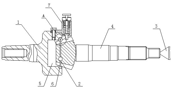
[0019] Embodiment 1: as figure 1 As shown, a bevel gear shaft tooth surface pitch cone positioning tool includes a tooling body 1 with a Morse taper handle, a floating steel ball retaining ring 2, a top 3 and a fast telescopic anti-rotation pin assembly 7. The floating steel ball The ball retaining ring 2 is set in the tooth groove at the front end of the processed product 4 and placed in the groove 5 provided at the right end of the tooling body 1 with a Morse taper shank, and the floating steel ball retaining ring 2 abuts against the groove. There are 6 limiting steps in the groove 5, the top 3 is against the center hole of the tail end of the processed product 4, and the product is held and rotated about 90 degrees to 135 degrees around the axis, so that the product is automatically centered and installed. Finish.

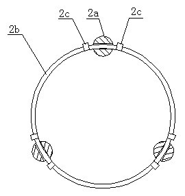
[0020] Such as figure 2 As shown, the floating steel ball retaining ring 2 includes three steel balls with holes 2a, steel wires 2b and limit stops 2c, the t...

Embodiment 2

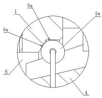
[0023] Embodiment 2: as Figure 5 with 6 As shown, wherein the floating steel ball retaining ring 2 includes four steel balls with holes 2a, steel wires 2b and limit stops 2c, the four steel balls with holes 2a are evenly distributed on the circumference of the steel wires 2b, and the steel balls with holes The aperture of 2a is larger than the diameter of the steel wire 2b, and the limit stoppers 2c are respectively arranged on the steel wire 2b and on both sides of the corresponding steel balls with holes 2a, and there is a certain distance between the limit stoppers 2c and the corresponding steel balls with holes 2a. spacing; as Figure 7 As shown, the perforated steel ball 2a abuts against the groove inner wall 5a and the limit step wall 6a at the limit step 6 respectively, the groove inner wall 5a and the limit step wall 6a form a right angle structure, and the limit step Point supports are formed on the steel balls with holes in the axial and radial directions to meet ...


PUM


Abstract

The invention discloses a bevel gear shaft tooth surface pitch cone locating tool, comprising a tool body provided with a Morse taper shank, a floating type steel ball retaining ring and a tip, wherein the floating type steel ball retaining ring is sheathed in a tooth space at the front end of a processed product and is arranged in a groove arranged at one end of the tool body provided with the Morse taper shank, the floating type steel ball retaining ring leans against a limit step in the groove, and the tip leans against in a central hole at the tail end of the processed product. In the invention, the structural design that the groove is arranged at the end part of the tool body provided with the Morse taper shank is coordinated with the floating type steel ball retaining ring sheathed in the tooth space at the end part of the process product, thus the shaft diameter of the processed product and the cone pitch circle of a gear can be ensured to be maintained on the same axial lead to the utmost extent, the geometric eccentricity of the gear and the shaft diameter is corrected to the utmost extent, the problem that a gear ring runs out in the processing process can be prevented, and the product accuracy is greatly improved.

Description

technical field [0001] The invention relates to the technical field of gear processing, in particular to a tooling for automatically centering and machining the shaft diameter of a conical (straight bevel, arc bevel) gear shaft by using a pitch cone of a gear tooth surface. Background technique [0002] Due to the geometric eccentricity and heat treatment deformation of the bevel gear shaft in the gear manufacturing process, it has long been a major problem in the gear manufacturing industry. The existing processing method is to use the center holes at both ends of the gear shaft to position the head frame lever to dial the part to process the shaft diameter, but in the existing processing method, if the concentricity accuracy of the pitch cone of the gear and the shaft diameter is not high , will produce periodic impact vibration during high-speed rotary transmission, so noise will be generated. Contents of the invention [0003] The purpose of the present invention is t...

Claims


Application Information

Patent Timeline
IPC IPC(8): B23F23/00
Inventor 曾向东
Owner CHONCHE GRP SICHUAN DANCHI PARTS & COMPONENTS CO LTD
Why Eureka
Try Eureka