Controllable coolant pump

一种冷却剂泵、冷却回路的技术,应用在泵控制、非变容式泵、机器/发动机等方向,能够解决阻碍燃烧室加温、复杂结构、冷却剂流昂贵机械机构等问题,达到结构保持简单的效果

Inactive Publication Date: 2011-08-10
SCHAEFFLER TECH AG & CO KG
View PDF6 Cites 18 Cited by
  • Summary
  • Abstract
  • Description
  • Claims
  • Application Information

AI Technical Summary

Problems solved by technology

In contrast, the problem arises during a cold start of the internal combustion engine that the coolant is already circulating through the cooling ducts, which prevents the heating of the combustion chamber and thus delays the attainment of the optimum operating temperature
[0006] Disadvantageously with such an arrangement is that the adjustment of the coolant flow by means of the displacement element has a complex mechanism and thus a complex construction.

Method used


Image

  • Controllable coolant pump
  • Controllable coolant pump
  • Controllable coolant pump

Examples


Embodiment Construction

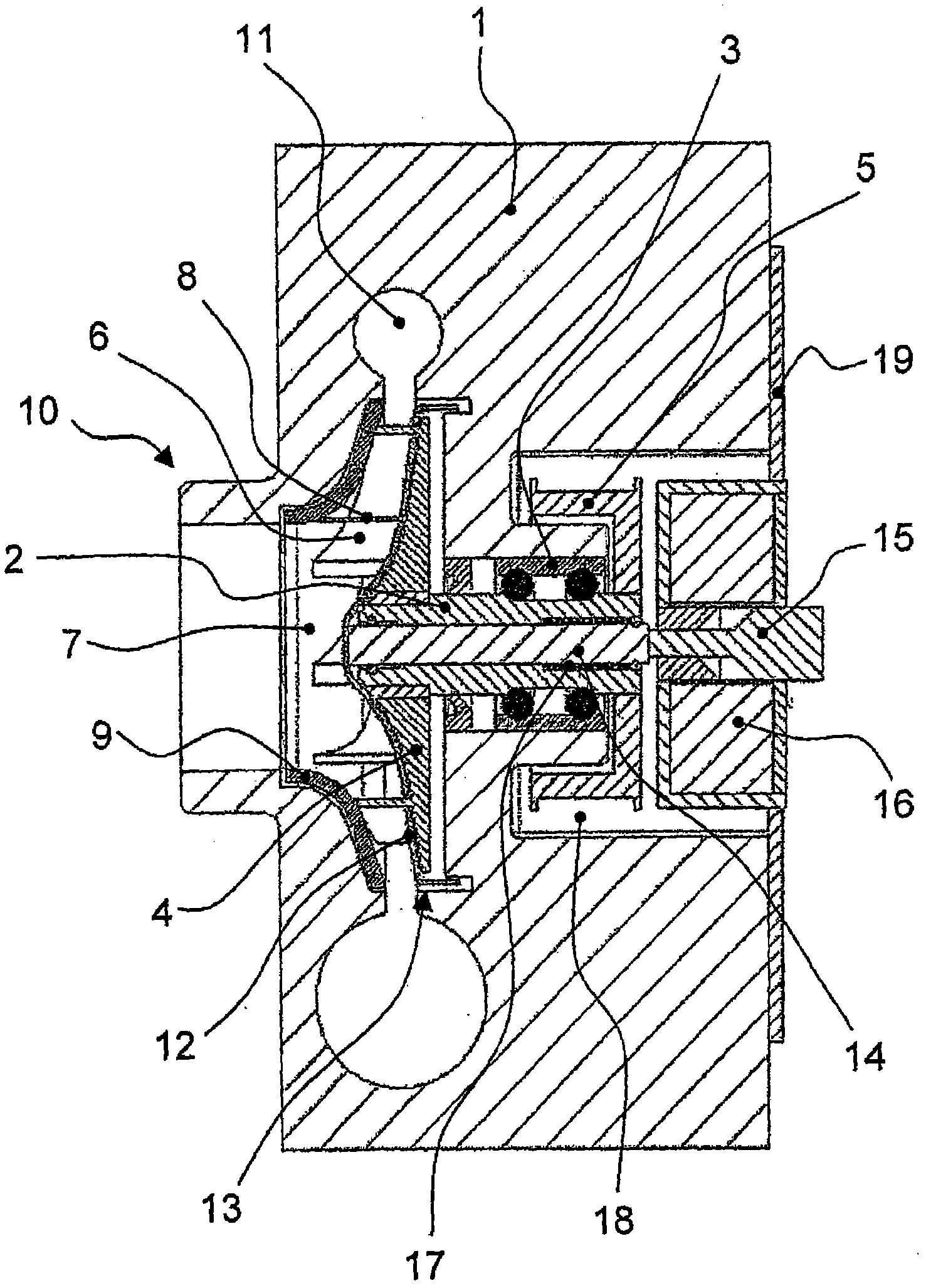
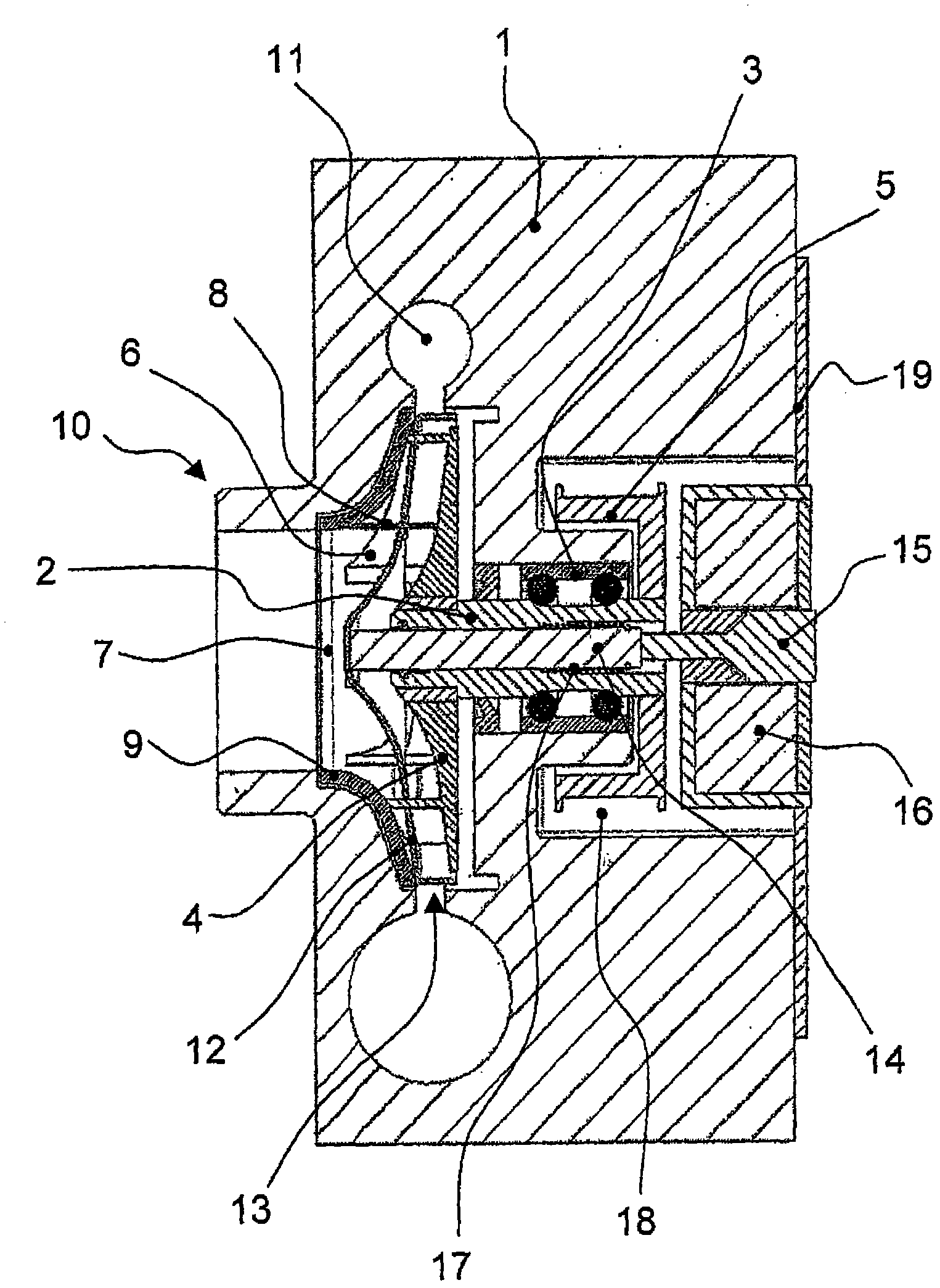
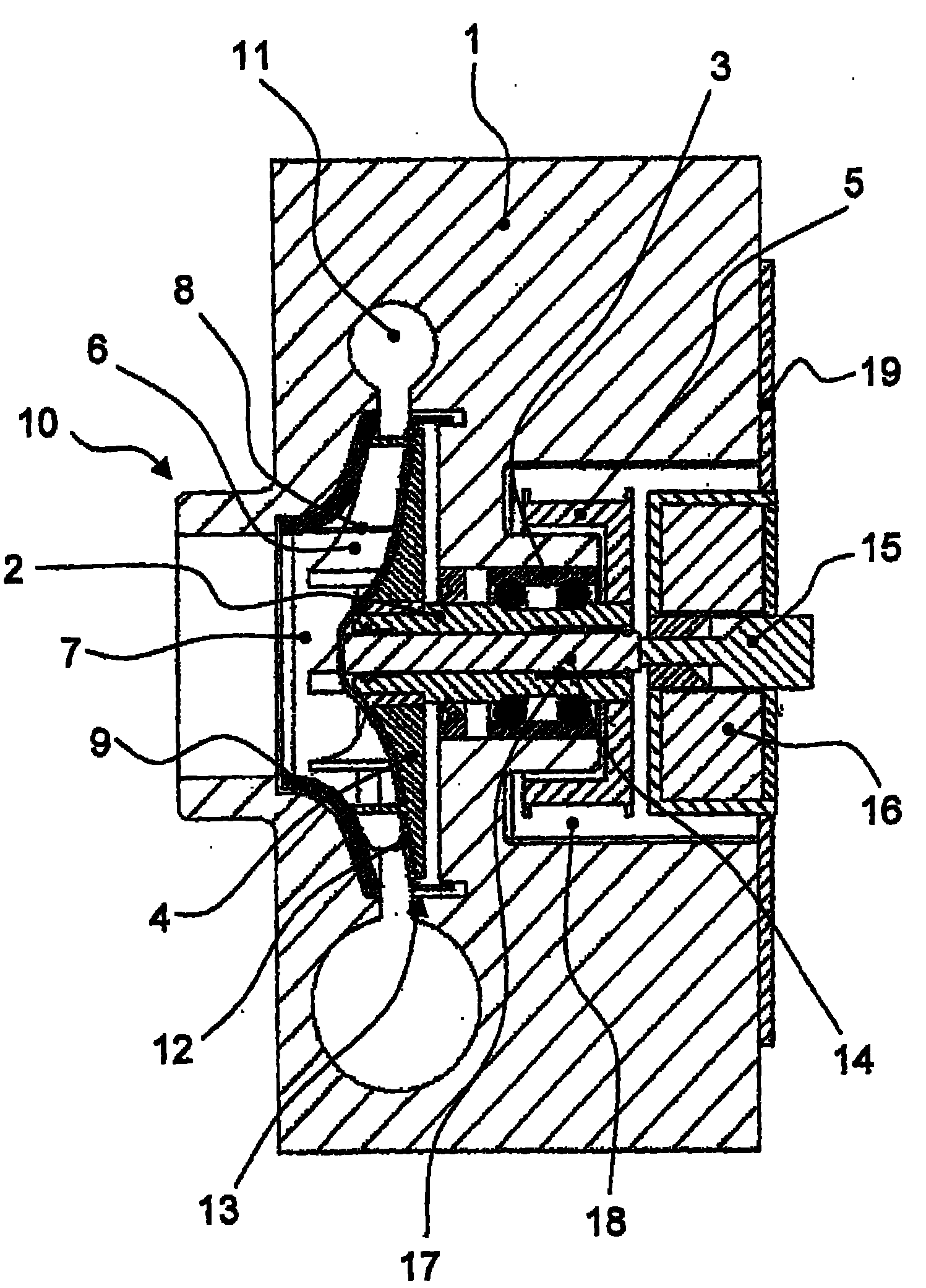
[0021] exist Figure 1a shows a sectional view of a coolant pump according to the invention having a hollow shaft 2 mounted in a pump housing 1 . Here, the hollow shaft 2 is rotatably mounted in a bore of the pump housing 1 via a double row ball bearing 3 and carries an impeller 4 at one end, while the hollow shaft 2 is fixed at its other end with a belt pulley 5 connect. With this pulley 5 the hollow shaft 2 can be driven via a belt drive of the internal combustion engine, not shown here. The impeller 4 has blades 6 which extend axially into a suction chamber 7 of the coolant pump. In addition, the impeller 4 is kept connected to the cover plate 9 via the axial connecting piece 8 . When the coolant pump is in operation, water is sucked into the suction chamber 7 via the suction connection 10 of the pump housing 1 by the joint rotation of the impeller 4 and the cover plate 9 and due to this generated by the impeller 4 and by the blades 6 is pushed into the annular channel 1...


PUM


Abstract

The invention relates to a controllable coolant pump for a cooling circuit of an internal combustion engine, having a pump housing (1), in which a hollow shaft (2) which can be driven through a belt pulley (5) is supported. An impeller (4) is fastened to an end of said hollow shaft, comprises blades (6) protruding into a suction chamber (7), and is rigidly connected to a cover disk (9) through axial webs (8), wherein water can be sucked into the suction chamber (7) through a suction connecting piece (10) of the pump housing (1) and transported into a ring channel (11) of the pump housing (1) over the blades (6) by the rotation of the impeller (4) together with the cover disk (9), wherein furthermore a guide disk (12) having a contour corresponding to the impeller (4) is arranged between the impeller (4) and cover disk (9), is guided over the axial webs (8), and can be moved axially through an actuating unit by means of a piston (14) placed within the hollow shaft (2).

Description

technical field [0001] The invention relates to an adjustable coolant pump for a cooling circuit of an internal combustion engine, the adjustable coolant pump having a pump housing in which a hollow shaft drivable by means of a belt pulley is supported, at one end of the hollow shaft An impeller is fixed on the top, the impeller has blades protruding into the suction chamber, and is fixedly connected to the cover plate through the axial connecting piece, wherein, through the common rotation of the impeller and the cover plate, water can be sucked through the pump casing The pipe connection is sucked into the suction chamber and can be conveyed by the vanes into the annular channel of the pump casing. Background technique [0002] In the field of internal combustion engines, water cooling of the engines has been widely used. Here, cooling water is pumped in a closed circuit by means of a coolant pump through cooling ducts in the area of ​​the cylinders for cooling the intern...

Claims


Application Information

Patent Timeline
Patent Type & Authority Applications(China)
IPC IPC(8): F04D15/00
CPCF04D15/0038F05D2270/62
Inventor 亚历山大·德拉海姆安德烈亚斯·内德尔爱德华·戈洛瓦泰-施米特延斯·舍费尔桑德拉·舍费尔
Owner SCHAEFFLER TECH AG & CO KG
Why Eureka
Try Eureka