Method for modifying a transparent electrode film

A transparent electrode film, modified technology, applied in the direction of circuits, electrical components, electrical solid devices, etc., can solve the problems of substrate deformation, insufficient production efficiency, resin deterioration and other problems, achieve high-efficiency resistivity, suppress thermal deterioration or Effects of thermal deformation and reduction of electrical resistivity

Active Publication Date: 2011-08-10
SUMITOMO CHEM CO LTD
View PDF3 Cites 2 Cited by
  • Summary
  • Abstract
  • Description
  • Claims
  • Application Information

AI Technical Summary

Problems solved by technology

[0003] However, in the conventional method described in Patent Document 1, the time required for the annealing treatment is long, and the production efficiency is not necessarily sufficient.
In addition, when the material of the substrate is an organic substance such as resin, there may be a problem of deformation of the substrate or deterioration of the resin due to the heat of the heating oven during the annealing treatment.

Method used


Image

  • Method for modifying a transparent electrode film
  • Method for modifying a transparent electrode film

Examples


Embodiment 1

[0032] A substrate (material: glass, thickness: 0.7 mm) was placed in a sputtering device (manufactured by FTS Corp., product name "FTS facing sputtering device"), and sputtered on the surface of the substrate under the conditions shown below. A transparent electrode film (material: ITO, thickness: 150 nm) was formed on the substrate to obtain a substrate with a transparent electrode film. The surface resistivity of the transparent electrode film on the obtained substrate with the transparent electrode film was 51.7 Ω / ㎡.

[0033] Film forming pressure: 0.5 Pa

[0034] Ar flow: 40 sec / m

[0035] Oxygen flow: 0.5 seconds / m

[0036] Input power: DC 1kW

[0037] Film formation rate: 11 nm / m

[0038] Target: ITO (10% mass SnO 2 ).

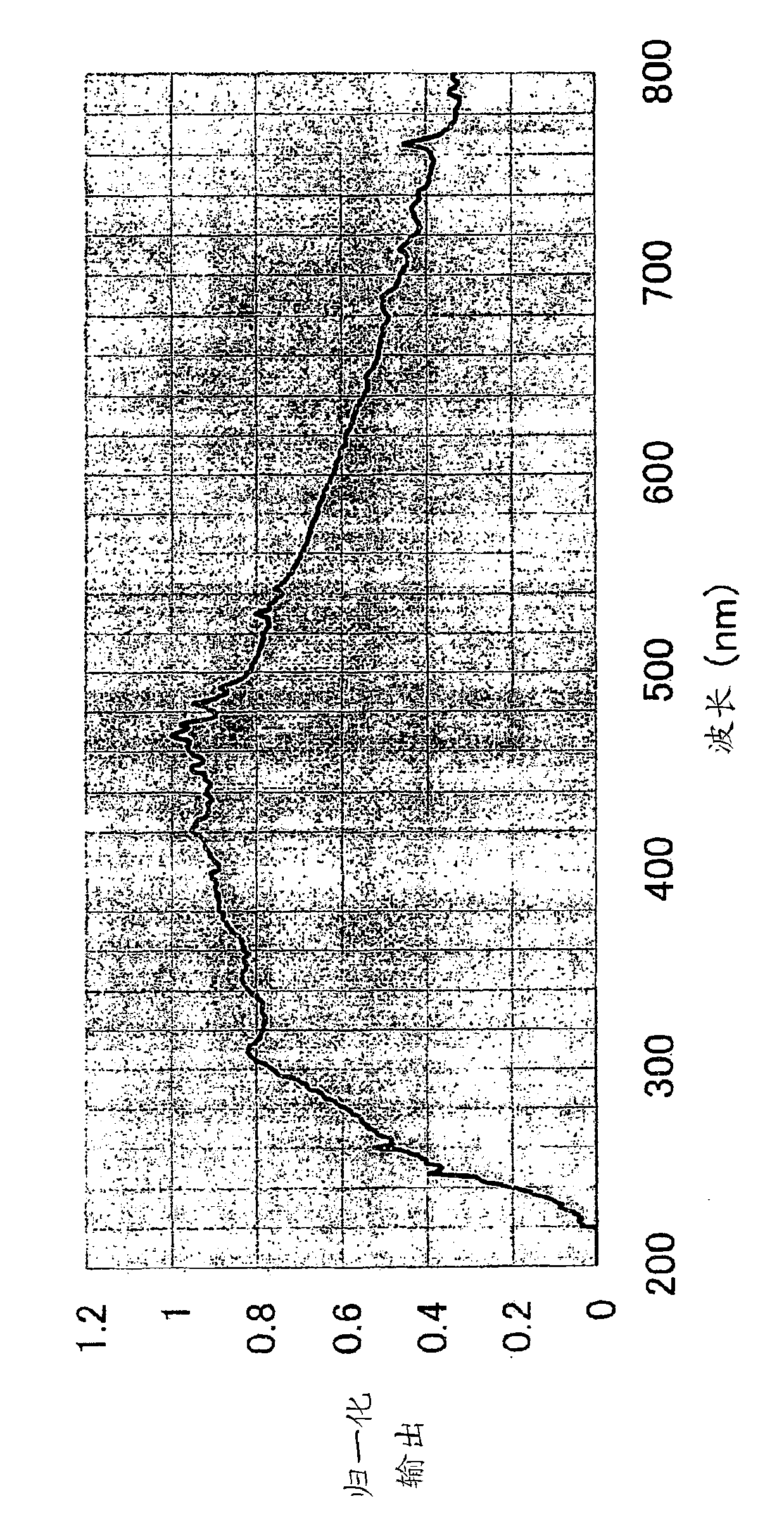
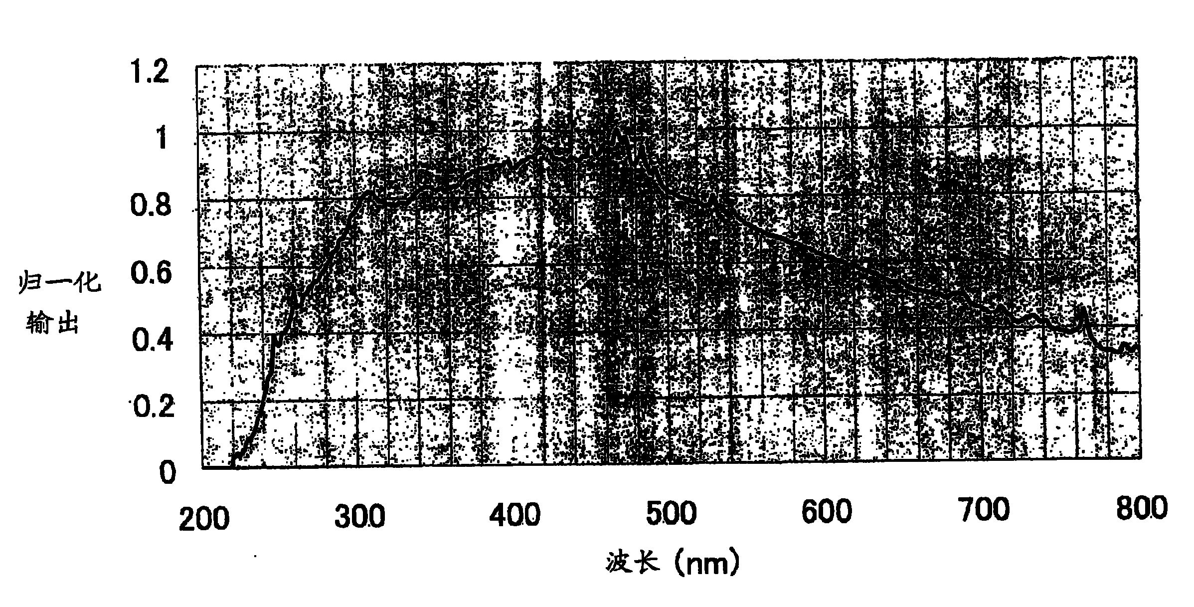
[0039] Next, using a flash annealing device manufactured by Usio Electric Co., Ltd., the surface of the transparent electrode film on the obtained substrate with a transparent electrode film was irradiated with a flash lamp, and the transparent el...

Embodiment 2

[0046] A substrate made of resin (material: polyethylene naphthalate, thickness: 125 μm) was used instead of the substrate (material: glass, thickness: 0.7 mm), and a film with a transparent electrode was obtained in the same manner as in Example 1 except that substrate, and the modified substrate with transparent electrode film. The surface resistivity of the transparent electrode film on the substrate with the transparent electrode film before modification was 53.2 Ω / μ. The surface resistivity of the transparent electrode film on the modified transparent electrode film-attached substrate was 18.4 Ω / Ω, and the substrate made of the resin was not deformed or discolored. Therefore, it was confirmed that according to the modification method of the transparent electrode film of the present invention, the surface resistivity of the transparent electrode film can be sufficiently reduced by annealing for a short time. It was also confirmed that the modification method of the transp...


PUM

PropertyMeasurementUnit
thicknessaaaaaaaaaa
thicknessaaaaaaaaaa
thicknessaaaaaaaaaa

Abstract

A method for modifying a transparent electrode film contained in a transparent electrode film-attached substrate having a substrate and the transparent electrode film formed on the substrate includes annealing the transparent electrode film by applying flash light having an optical pulse duration time of 0.1 msec to 10 msec to the transparent electrode film using a flash lamp, thereby heating thetransparent electrode film.

Description

technical field [0001] The present invention relates to a method of modifying and lowering the resistivity of a transparent electrode film on a substrate with a transparent electrode film used in a light-emitting element, and a method of manufacturing a substrate with a transparent electrode film using the method. Background technique [0002] In a light-emitting element such as an organic electroluminescent element (organic EL element), a transparent electrode film is generally used as an electrode on the side of the light output port for taking out light from the light-emitting layer. In addition, in order to improve the luminous brightness of the light-emitting layer, it is preferable to reduce the resistivity of the transparent electrode film as much as possible. Therefore, while investigating the technology of forming a transparent electrode film with a lower resistivity, it is also studied to make the resistivity of the transparent electrode film after forming the trans...

Claims


Application Information

Patent Timeline
Patent Type & Authority Applications(China)
IPC IPC(8): H01B13/00C23C14/58
CPCC23C14/086C23C14/5806H01L33/42H01L51/5206H01L51/442H01L2251/308H10K30/82H10K50/81H10K2102/103H01B13/00C23C14/58
Inventor 黑田俊也
Owner SUMITOMO CHEM CO LTD
Why Eureka
Try Eureka