
Mechanical and electrical piston directly-driven reciprocating pump

A direct drive, reciprocating pump technology, applied in the direction of machines/engines, pumps, mechanical equipment, etc., can solve the problems of high valve opening frequency, low flow rate, high energy consumption of pumps, etc., achieve simple and compact structure, improve stability, and efficiency high effect

Inactive Publication Date: 2011-08-17
HEFEI HUAYU RUBBER EQUIP
View PDF3 Cites 7 Cited by
  • Summary
  • Abstract
  • Description
  • Claims
  • Application Information

AI Technical Summary

Problems solved by technology

[0003] 1. The driving piston stroke of the crankshaft connecting rod mechanism is short, and the corresponding valve opening frequency is high and the service life is short;
[0004] 2. The piston movement is a variable speed movement, the energy consumption of the pump is high, and the flow and lift have large pulsations;
[0005] 3. The flow rate is small, and reciprocating pumps with large flow rate are rarely seen in the market at present;
[0006] 4. The power sources of reciprocating pumps in the prior art are mostly AC motors, linear motors and hydraulic drives, etc., and cannot be used in the case of no electricity or power failure
[0007] So far, no reciprocating pump has been retrieved and seen that has both internal combustion engine and electric motor, internal combustion engine and reciprocating pump piston direct drive type

Method used


Image

  • Mechanical and electrical piston directly-driven reciprocating pump
  • Mechanical and electrical piston directly-driven reciprocating pump
  • Mechanical and electrical piston directly-driven reciprocating pump

Examples


no. 1 example

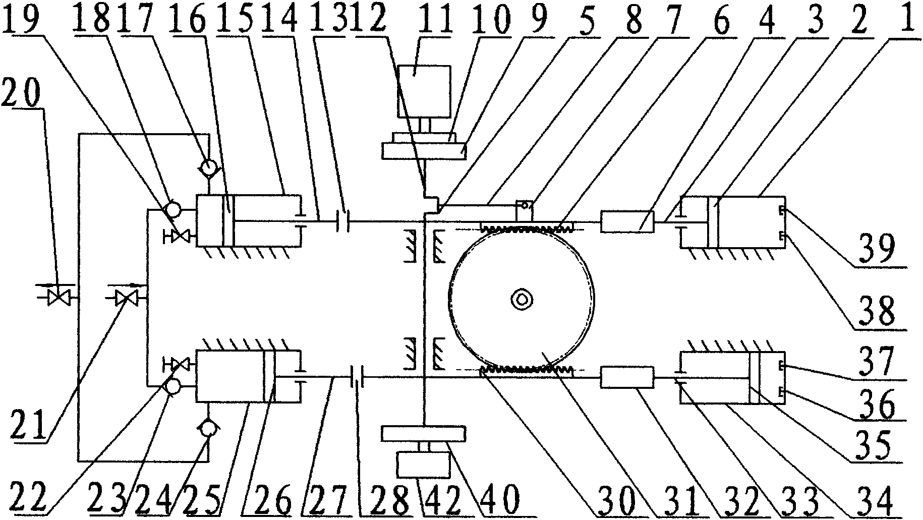
[0024] The first embodiment: attached figure 1 It is a single-group double-cylinder mechanism pump.

[0025] An electromechanical dual-purpose piston direct-driven reciprocating pump, the internal combustion engine part is mainly composed of a body, a gas distribution mechanism, an oil supply system, a lubrication system, a cooling system, and a starting device; the key to the invention lies in the piston rod of the internal combustion engine and the piston rod of the reciprocating pump , is combined by a coupling and a rack bar clutch group, mainly composed of internal combustion engine cylinders 1 and 34, internal combustion engine pistons 2 and 35, internal combustion engine piston rods 3 and 33, rack bar clutch 4, rack bar 6, and rack bar Connecting piece 7, connecting rod 8, crankshaft 12, transmission wheel 9, motor clutch 10, motor 11, coupling 13 and 28 and 41, starting wheel 40, starter 42, reciprocating pump cylinder 15 and 25, reciprocating pump piston 16 and 26, r...

no. 2 example

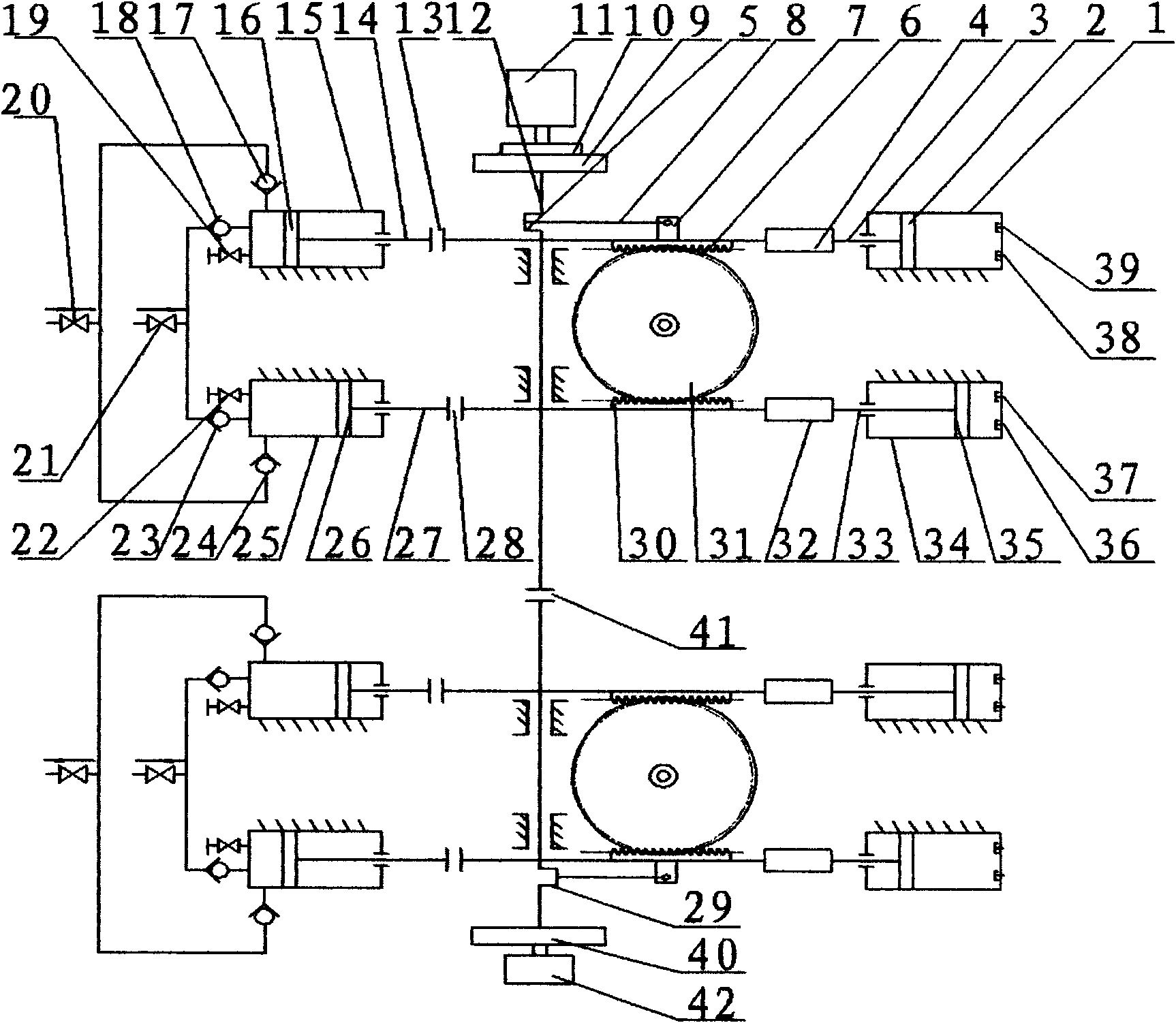
[0028] The second embodiment: attached figure 2 It is two sets of four-cylinder mechanism pumps.

[0029]The working principle of this structure is the same as that of the first embodiment. One of the differences is that the internal-combustion engine cylinder group and the reciprocating pump cylinder group are twice as many as in the first embodiment, and are two groups; the second is that the crankshaft 12 is lengthened, and an inflection path 29 is added, and the crankshaft 12 can adopt a shaft coupling 41 connections or whole. According to the actual operating conditions and the requirements of output flow, through the rack bar clutches 4 and 32, the functions of the rack bars 6 and 30 and the internal combustion engine piston rods 3 and 33 can be clutched, and single or double sets of internal combustion engine cylinders can be selected to work.

no. 3 example

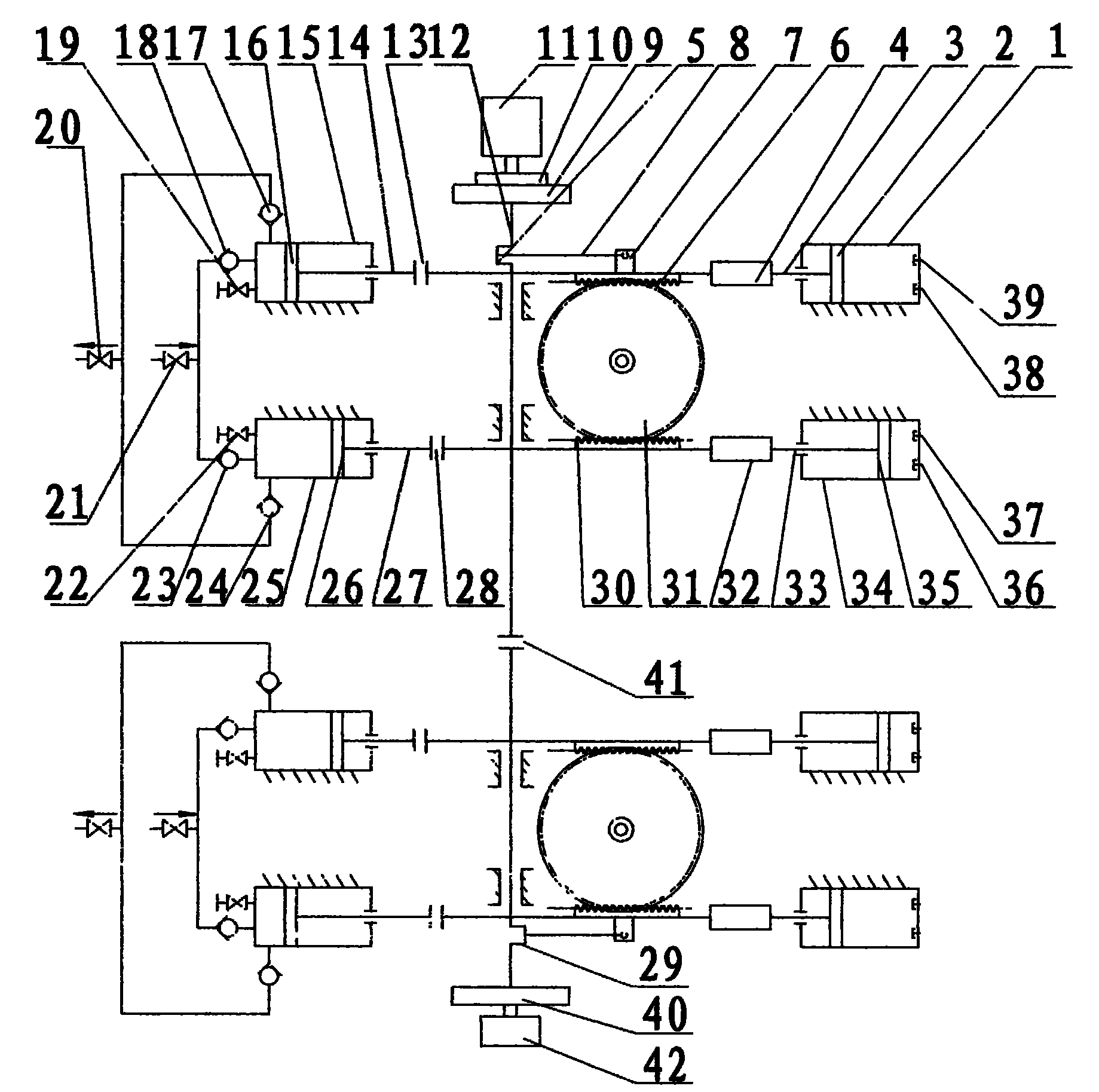
[0030] The third embodiment: combined with figure 2 be explained.

[0031] Working principle is the same as that of the first embodiment. According to the actual working conditions and the requirements of the output flow, the length of the crankshaft 12 and the number of turning diameters 29 can be increased, connected by multiple couplings 41, and a combination of two or more internal combustion engine cylinder groups and reciprocating pump cylinder groups can be selected. , through the rack bar clutch 4 and 32 can make the rack bar 6 and 30, internal combustion engine piston rod 3 and 33 clutch function, can choose a single set of internal combustion engine cylinders to drive multiple sets of reciprocating pump cylinders to work, or select multiple sets of internal combustion engine cylinders to drive Multiple groups of reciprocating pump cylinders work.

[0032] When there is electric power, can adopt separation rack bar clutch 4 and 32, engage the motor clutch 10 betwee...


PUM


Abstract

The invention discloses a mechanical and electrical piston directly-driven reciprocating pump, which mainly comprises an internal-combustion engine cylinder, a reciprocating pump cylinder, a rack rod, a rack rod clutch, a coupling, a start wheel, a starter, a crankshaft, a connecting rod, a motor clutch, a motor and the like. Pistons of an internal-combustion engine cylinder group and a reciprocating pump cylinder group are in a direct-drive mode, so that the mechanical and electrical piston directly-driven reciprocating pump not only has the characteristics of the reciprocating pump, but also is simple and compact in structure, low in energy consumption, high in efficiency and stable in flow and pressure; two powers of an internal-combustion engine and the motor can be interchanged for use, so that operation requirements for the industries of fire protection, mines and oil fields can be met, particularly the operation requirements in situations of no electric power or emergency power failure can be met.

Description

technical field [0001] The invention relates to a reciprocating pump combined with an internal combustion engine, especially a reciprocating pump with a large flow rate and a high lift, and an electromechanical dual-purpose piston direct-coupled drive reciprocating pump used in the state of no electricity. Background technique [0002] Known existing reciprocating pumps mostly use a crankshaft-connecting rod mechanism to drive the piston to reciprocate, which has the advantages of high discharge pressure, high efficiency, and unique good self-priming performance. But also there are following deficiencies: [0003] 1. The driving piston stroke of the crankshaft connecting rod mechanism is short, and the corresponding valve opening frequency is high and the service life is short; [0004] 2. The piston movement is a variable speed movement, the energy consumption of the pump is high, and the flow and lift have large pulsations; [0005] 3. The flow rate is small, and recipro...

Claims


Application Information

Patent Timeline
IPC IPC(8): F04B17/05
Inventor 王健军张高峰马国粹
Owner HEFEI HUAYU RUBBER EQUIP
Learn More