Low-temperature medium liquefaction device

A low-temperature medium and liquefaction device technology, applied in the field of liquefaction, can solve the problems of increasing the gas demand of low-temperature medium, easy to form natural convection, unused heat transfer area, etc., and achieve the effect of avoiding convective heat transfer

Active Publication Date: 2011-08-17
中国船舶重工集团公司第七一二研究所
View PDF4 Cites 7 Cited by
  • Summary
  • Abstract
  • Description
  • Claims
  • Application Information

AI Technical Summary

Problems solved by technology

The main disadvantages of the first structure are: (1) The bottom surface of the low-temperature end of the cold head of the refrigerator transfers cold energy to the cooling medium through the cold head heat exchanger, but the side surfaces of the low-temperature end are all in a vacuum environment, and the heat transfer area of ​​this part is not used; (2) Since the cold head of the refrigerator is in a vacuum environment, the installation, maintenance and disassembly of the cold head of the refrigerator are very inconvenient
The Dewar vacuum is destroyed when the cold head is disassembled, and it needs to be vacuumed again after each reinstallation. Due to the long vacuuming time and complicated pumping process, this brings great inconvenience to the maintenance operation of the cryogenic medium liquefaction device sex
The main disadvantage of the second structure is that the wide-mouth Dewar neck tube is too large in diameter, which is easy to form natural convection, resulting in large heat leakage. At the same time, the Dewar inner cavity has a large space, which increases the gas demand for low-temperature media.

Method used


Image

  • Low-temperature medium liquefaction device
  • Low-temperature medium liquefaction device
  • Low-temperature medium liquefaction device

Examples


Embodiment 1

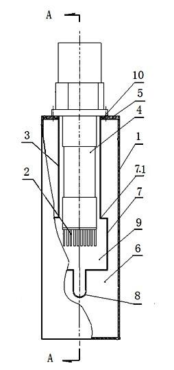
[0025] Example 1: Such as figure 1 , 2 , shown in 3: a low-temperature medium liquefaction device has a Dewar 1 and a heat exchange assembly; 8; wherein the Dewar 1, casing 3, liquid collecting pipe 7 and transmission pipe 8 can be made of stainless steel pipes, and the heat exchanger 2 is made of high thermal conductivity materials, such as red copper. The upper end of the casing 3 is sealed and fixedly connected to the upper part of the inner cavity of the Dewar 1, and the lower end is sealed and fixedly communicated with the liquid collecting pipe 7; one end of the transmission pipe 8 is sealed and fixedly connected with the lower part of the liquid collecting pipe 7, and the middle part is sealed and fixed with the Dewar 1 The other end leads to the outside of Dewar 1; the cold head 4 of the refrigerator is a GM refrigerator cold head, the upper part is sealed and fixedly connected with the Dewar 1, the lower part is in the inner cavity of the casing 3, and the lower en...

Embodiment 2

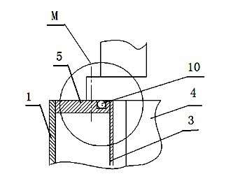
[0026] Example 2: The difference from Example 1 is that the "O"-shaped sealing ring 10 between the cold head 4 of the refrigerator and the flange 5 is a metal sealing ring; the inner wall of the vacuum area 6 and the outer wall of the Dewar 1 are all sealed. Multi-layer heat insulation layer; the outer wall of casing 3 has a heat insulation layer made of heat insulation material. This embodiment is a heat insulation layer made of ten layers of double-sided aluminized polyester film and glass fiber cloth; For installation, the connecting port 7.1 is on the upper end face; there is a gap of 0.5 mm between the inner wall of the casing 3 and the cold head 4 of the refrigerator.

Embodiment 3

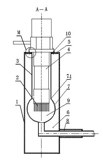
[0027] Embodiment 3: Such as figure 2 , 3 As shown in , 4, the difference from Embodiment 1 is that it is an integrated cryogenic medium liquefaction device with 2 heat exchange components, with 1 Dewar 1 and 2 heat exchange components; each heat exchange component includes 1 A heat exchanger 2, a sleeve pipe 3 and a refrigerator cold head 4; each heat exchange component has a liquid collection pipe 7 and a transmission pipe 8; the upper end of the sleeve pipe 3 is sealed and fixedly connected to the Dewar 1 The upper part of the inner cavity and the lower end are sealed and fixedly communicated with the liquid collecting pipe 7; one end of the transmission pipe 8 is sealed and fixedly connected with the lower part of the liquid collecting pipe 7, the middle part is sealed and fixedly connected with the Dewar 1, and the other end leads to the outside of the Dewar 1; The upper part of the refrigerator cold head 4 is sealed and fixedly connected with the Dewar 1, the lower...


PUM


Abstract

The invention relates to a low-temperature medium liquefaction device which comprises a Dewar and a heat exchange assembly, wherein the heat exchange assembly comprises a heat exchanger, a sleeve, a refrigerator cold head, a collector tube and a transmission tube; the upper end of the sleeve is hermetically and fixedly connected to the upper part of an inner cavity of the Dewar, and the lower end of the sleeve is hermetically and fixedly communicated with the collector tube; one end of the transmission tube is hermetically and fixedly communicated with the lower part of the collector tube, the middle part of the transmission tube is hermetically and fixedly connected with the Dewar, and the other end of the transmission tube is communicated to a cooled object outside the Dewar; the upper part of the refrigerator cold head is hermetically and fixedly connected with the Dewar, the lower part of the refrigerator cold head is arranged in the inner cavity of the sleeve, and the lower end of the refrigerator cold head is connected with the heat exchanger. The low-temperature medium liquefaction device disclosed by the invention has the advantages that: the heat transfer area at the low-temperature end of the refrigerator cold head is fully utilized, the heat leakage quantity is reduced, the working efficiency is improved, the energy resources are saved, the convenience for assembly and disassembly is achieved, and the manufacturing and maintaining cost is reduced.

Description

technical field [0001] The invention relates to a low-temperature medium liquefaction device, which is particularly suitable for the situation where a single or multiple refrigerators are required to integrate liquefaction of low-temperature medium, and belongs to the technical field of liquefaction. Background technique [0002] The refrigerator integration technology in the prior art mainly adopts two methods, the first one is: the cold head of the refrigerator is placed in a vacuum, the end of the cold head of the refrigerator is connected to a heat exchanger, and the heat exchanger is connected to a low-temperature medium (such as liquid neon, The container where the liquid hydrogen is located is welded, and the low-temperature medium in the container is cooled and liquefied by a heat exchanger; the second is that the cold head of the refrigerator is placed in the wide-mouth Dewar liner, and the low-temperature liquid medium is placed on the bottom of the wide-mouth Dewar...

Claims


Application Information

Patent Timeline
Patent Type & Authority Applications(China)
IPC IPC(8): F17C13/00
Inventor 陈伟代义军郑军方芳
Owner 中国船舶重工集团公司第七一二研究所
Why Eureka
Try Eureka