
LED (light emitting diode) lamp bulb with high light-emitting rate

A technology of LED light bulbs and LED light strips, applied in the direction of light sources, lampshades, electric light sources, etc., can solve the problems of low light output rate and poor heat dissipation performance, achieve the effects of no electromagnetic radiation, improve heat dissipation performance, and improve light utilization rate

Inactive Publication Date: 2011-08-17
翁小翠
View PDF7 Cites 9 Cited by
  • Summary
  • Abstract
  • Description
  • Claims
  • Application Information

AI Technical Summary

Problems solved by technology

[0004] In order to overcome the shortcomings of the existing LED lamps, such as low light output rate and poor heat dissipation performance, the present invention provides a high light output rate LED bulb with improved light output rate and enhanced heat dissipation performance.

Method used


Image

  • LED (light emitting diode) lamp bulb with high light-emitting rate
  • LED (light emitting diode) lamp bulb with high light-emitting rate
  • LED (light emitting diode) lamp bulb with high light-emitting rate

Examples


Embodiment Construction

[0035] The present invention will be further described below in conjunction with the accompanying drawings.

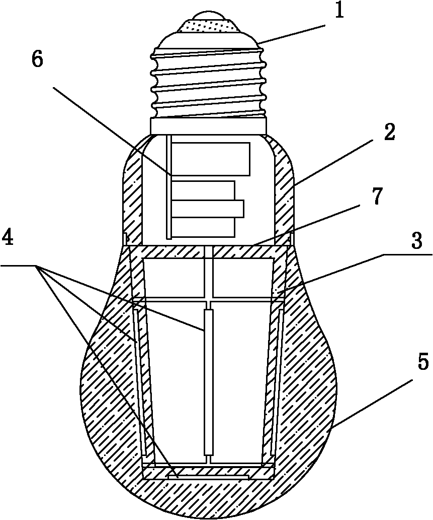
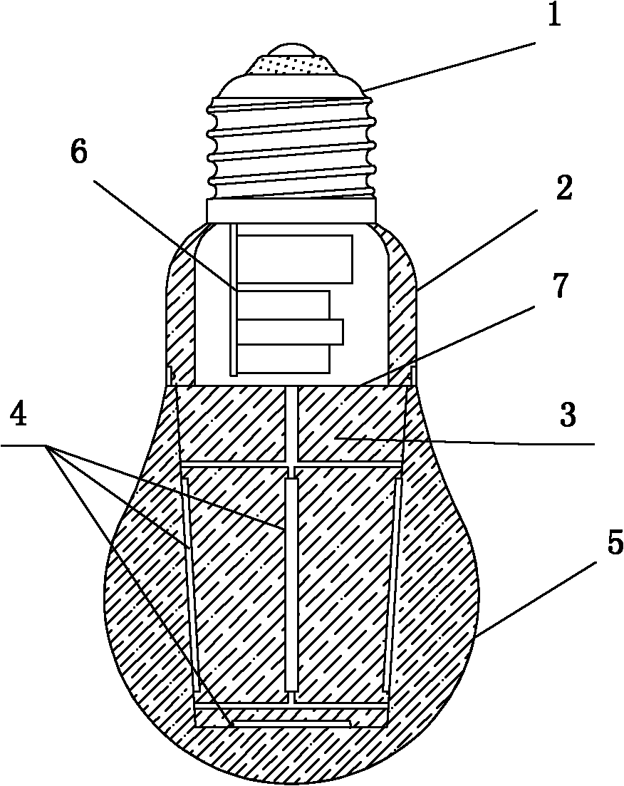
[0036] refer to Figure 1 to Figure 8 , a high light output LED light bulb, including a lamp base 1, a lamp housing 2, an LED driver 6 and a bulb cover 5, the lamp base 1 is connected to the upper end of the lamp housing 2, and the LED driver 6 is installed in the lamp housing 2, so The lower end of the lamp housing 2 is connected to the bulb cover 5. The LED bulb also includes a transparent lamp post 3 with high thermal conductivity. The transparent lamp post 3 is located in the bulb cover 5. The lower end of the lamp housing 2 is connected, and the high light output rate LED light bar 4 is installed on the transparent lamp post 3. The high light output rate LED light bar 4 includes a plurality of LED chips connected in series in sequence. The transparent lamp post 3 The cavity between the outside and the bulb cover 5 is filled with a transparent or translucent fille...


PUM


Abstract

The invention relates to an LED (light emitting diode) lamp bulb with a high light-emitting rate, comprising a lamp holder, a lamp shell, an LED driver and a lamp bulb cover, wherein the lamp holder is connected with the upper end of the lamp shell, the LED driver is arranged in the lamp shell, the lower end of the lamp shell is connected with the lamp bulb cover, the LED lamp bulb also comprises a transparent lamp post with high heat-conducting property, the transparent lamp post is arranged in the lamp bulb cover, the upper part of the transparent lamp post is connected with the lower end of the lamp shell, an LED lamp bar with a high light-emitting rate is arranged on the transparent lamp post and comprises a plurality of LED chips which are connected in series, transparent or semitransparent high heat-conduction fillers are filled in a cavity between the outer side of the transparent lamp post and the lamp bulb cover. For the LED lamp bulb with the high light-emitting rate, the light-emitting rate is improved and the heat dispersion property is enhanced.

Description

technical field [0001] The invention relates to an LED light bulb. Background technique [0002] In the existing LED light bulbs, LED chips are usually installed on the bottom surface of the substrate, and the LED substrate is usually made of a material with good thermal conductivity. The substrate is provided with a power connection interface, and the power connection interface is electrically connected to the power connection line. A printed circuit is provided, and a plurality of LED chips are arranged on the substrate, and the LED chips include a current-limiting resistor and a voltage stabilizer, and the current-limiting resistor and the voltage stabilizer are both connected to the printed circuit. [0003] Since the light emitted by the LED chip diverges downward, its irradiation range is the part below the substrate, that is, to achieve 2π light output, and part of the light is irradiated to the bottom surface of the substrate, which reduces the light output rate of t...

Claims


Application Information

Patent Timeline
Patent Type & Authority Applications(China)
IPC IPC(8): F21S2/00F21V29/00F21V19/00F21V7/00F21V23/04F21Y101/02
CPCF21Y2101/02F21V3/02F21K9/1355F21V29/24H05B33/0809H05B33/0803F21V29/85F21K9/23F21Y2115/10H05B45/30H05B45/37
Inventor 翁小翠
Owner 翁小翠
Learn More