Multi-phase optical fiber embedded power cable

A power cable and embedded technology, which is applied in the field of multi-phase electric optical fiber embedded power cables, can solve the problems of easy aging and failure of optical fiber cables, and achieve the effect of low cost and improving the degree of informatization.

Active Publication Date: 2011-08-17
SHANGHAI OUYI INTELLIGENT NETWORK +1
View PDF7 Cites 12 Cited by
  • Summary
  • Abstract
  • Description
  • Claims
  • Application Information

AI Technical Summary

Problems solved by technology

Therefore, when working with conventional communication optical fiber composite cables, the optical fiber cables are prone to aging and failure.

Method used


Image

  • Multi-phase optical fiber embedded power cable
  • Multi-phase optical fiber embedded power cable
  • Multi-phase optical fiber embedded power cable

Examples


Embodiment 1

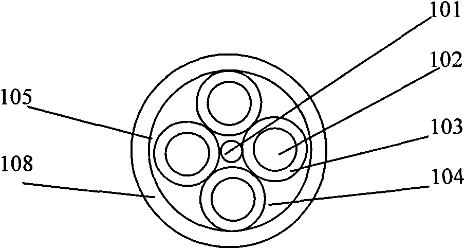
[0023] refer to figure 2 As shown, the present invention includes a multi-phase electric fiber embedded power cable, which includes an optical fiber cable 101, several cable assemblies clamping the optical fiber cable 101, a polymer material filling rope 104 surrounding the optical fiber cable 101 and the cable assembly , the wrapping layer 105 surrounding the optical fiber cable 101 and the cable assembly and the polymer material filling rope 104, the outer sheath 108 surrounding the wrapping layer 105; in the present invention, the copper core cable assembly is preferably 3 groups, which can be The fiber optic cable 101 is clamped. The cable assembly includes a copper core conductor 102 and an XLPE insulating layer 103 wrapping the copper core conductor 102 .

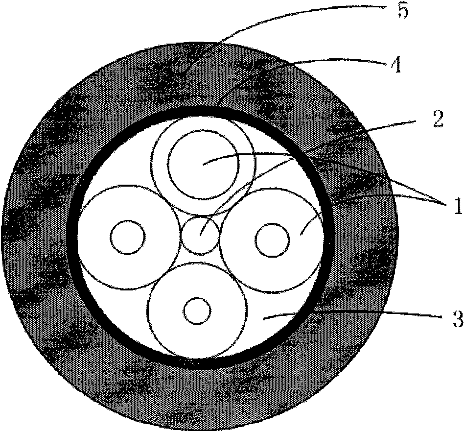
[0024] specific reference figure 1 , the multi-core special structure optical fiber cable used in the patent of the present invention, which includes a glass fiber reinforced resin composite (FRP) strengthening cor...

Embodiment 2

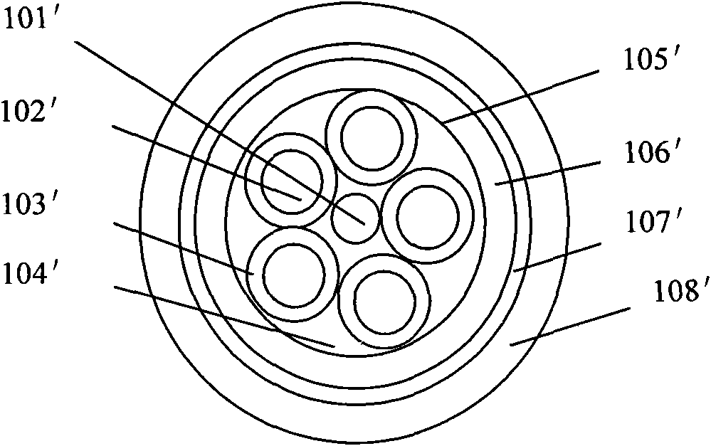
[0034]refer to image 3 As shown, the difference between this embodiment and the first embodiment is that: a polyethylene inner sheath '106 surrounding the wrapping layer 105' and a polyethylene inner sheath '106 surrounding the wrapping layer 105' are provided between the wrapping layer 105' and the outer sheath 108'. Metal armor 107' of sheath 106'.

[0035] Specifically, a multi-phase electrical fiber embedded power cable, which includes an optical fiber cable 101', several cable assemblies clamping the optical fiber cable 101', a filling rope 104' surrounding the optical fiber cable 101' and the cable assembly, wrapping The optical fiber cable 101', the cable assembly and the wrapping layer 105' of the filling rope 104' and the outer sheath 108' surrounding the wrapping layer 105'; the cable assembly includes a copper core conductor 102' and a wrapped copper core conductor XLPE insulating layer 103' of 102'; said optical fiber cable 101' includes a fiber-reinforced compos...


PUM

PropertyMeasurementUnit
dielectric strengthaaaaaaaaaa

Abstract

The invention relates to a multi-phase optical fiber embedded power cable. The power cable comprises an optical fiber cable, a plurality of cable assemblies for clamping the optical fiber cable, filler yarns, a lapped layer and an outer sheath, wherein the filler yarns surround the optical fiber cable and the cable assemblies; the lapped layer wraps up the optical fiber cable, the cable assemblies and the filler yarns; the outer sheath surrounds the lapped layer; the cable assemblies comprise copper core conductors and insulating layers wrapping up the copper core conductors; the optical fiber cable comprises a fiber reinforced composite strengthened core, a plurality of optical fibers for clamping the strengthened core, filled strips, an aramid fiber layer and an outer sheath; the filledstrips surround the strengthened core and the optical fibers; the aramid fiber layer wraps up the fiber reinforced composite strengthened core, the optical fibers and the polyethylene filled strips; and the outer sheath covers the aramid fiber layer. The invention provides low-cost and convenient schemes such as integration of optical and power cables into one and one cable with multiple purposesfor fiber to the home, four networks in one (power, telephone, television and computer), ammeter remote metering and interaction with power consumers of the smart grid.

Description

technical field [0001] The patent of the present invention relates to a special power cable, especially a multi-phase electric optical fiber embedded power cable, which is used for 400v low-voltage power supply network lines. Background technique [0002] In the construction of smart grid, it is necessary to strengthen the technical means of user load measurement monitoring and information communication at the end of the power grid (400V power supply network). [0003] Due to the current power carrier communication technology implemented on conventional power cables, due to its low speed, low communication success rate, and low reliability, it can no longer meet the needs of large-capacity real-time information communication for remote control, measurement, and monitoring of electric power in smart grids. [0004] In the construction of an information society, as telephones, computers, and televisions enter thousands of households, enterprises engaged in telecommunications, ...

Claims


Application Information

Patent Timeline
Patent Type & Authority Applications(China)
IPC IPC(8): H01B9/00H01B11/22H01B5/10H01B7/17H01B7/29H01B3/44H01B3/38
CPCG02B6/4416G02B6/4432
Inventor 吴海生王勇成俞佩瑜徐蔚
Owner SHANGHAI OUYI INTELLIGENT NETWORK
Why Eureka
Try Eureka