
Boost converter with built-in transformer and voltage-doubling unit of switching capacitor

A technology of switched capacitors and transformers, which is applied in the field of DC-DC converters, can solve the problems of large switching loss, difficult to achieve, and large voltage stress of power switching tubes, and achieves the advantages of reducing conduction loss, fewer accessory components, and improving efficiency. Effect

Inactive Publication Date: 2011-08-17
ZHEJIANG UNIV
View PDF5 Cites 5 Cited by
  • Summary
  • Abstract
  • Description
  • Claims
  • Application Information

AI Technical Summary

Problems solved by technology

[0002] The conventional boost DC-DC converter has a simple structure and is widely used, but the power switch of the converter works in a hard switching state, the switching loss is relatively large, the voltage stress of the power switch tube is relatively large, and the output diode’s reverse The recovery problem is serious, and in high-gain applications, a high switching duty cycle is required, which is difficult to achieve
In recent years, some high-gain Boost converters using series switched capacitor units have been studied successively. This method needs to connect multiple switched capacitor units in series to achieve high-gain conversion. The circuit is more complicated, the reverse recovery of the freewheeling diode is serious, and the output current ripple Big

Method used


Image

  • Boost converter with built-in transformer and voltage-doubling unit of switching capacitor
  • Boost converter with built-in transformer and voltage-doubling unit of switching capacitor
  • Boost converter with built-in transformer and voltage-doubling unit of switching capacitor

Examples


Embodiment Construction

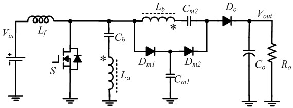
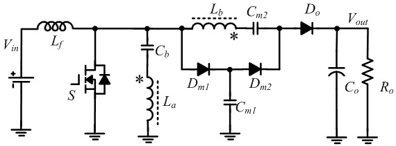
[0009] see figure 1 , the present invention's built-in transformer and the Boost converter of the voltage doubler unit of the switched capacitor, including two power switch tubes S , an input filter inductor L f , a DC blocking capacitor C b , a clamping diode D m1 , a clamp capacitor C m1 , a freewheeling diode D m2 , a switched capacitor C m2 , an output diode D o , an output capacitor C o and a built-in transformer with two windings L a , L b , input filter inductance L f One end of the power supply V in The positive terminal is connected, the input filter inductor L f The other end of the power switch and the S The source and clamping diodes of the D m1 The anode and DC blocking capacitor C b One end and the second winding of the built-in transformer L b Connected to one end of the DC blocking capacitor C b The other end of the built-in transformer with the first winding of the L a connected to one end, the clamping diode D m1 The catho...


PUM


Abstract

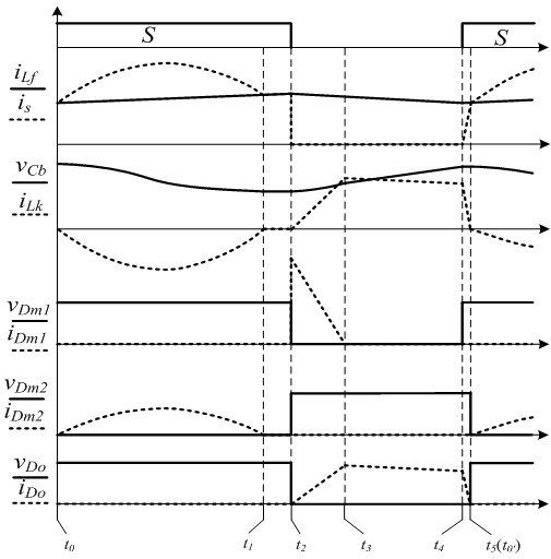
The invention discloses a Boost converter with a built-in transformer and a voltage-doubling unit of a switching capacitor, which comprises a power switching tube, an input filtering inductor, a blocking capacitor, a clamping diode, a clamping capacitor, a fly-wheel diode, the switching capacitor, an output diode, an output capacitor and a built-in transformer with two windings. The leakage inductance of the built-in transformer is utilized for realizing zero-current switching-on of the power switching tube and eliminating the backward recovery problem of the output diode and the clamping diode, a passive clamping circuit comprising the clamping diode and the clamping capacitor is utilized for realizing soft switching-off of the power switching tube and non-loss transfer of leakage inductance energy, the leakage inductance and resonance of the blocking capacitor are utilized for eliminating the backward recovery problem of the fly-wheel diode, the voltage-doubling unit comprising the built-in transformer and the blocking capacitor is utilized for realizing high-gain output of the converter and reducing the voltage stress of a power device, an additional power switch is not required, no energy loss elements exist in a circuit, and the structure is simple.

Description

technical field [0001] The invention relates to a DC-DC converter. Specifically, it is a Boost converter with a built-in voltage doubler unit of a transformer and switched capacitors. Background technique [0002] The conventional boost DC-DC converter has a simple structure and is widely used, but the power switch of the converter works in a hard switching state, the switching loss is relatively large, the voltage stress of the power switch tube is relatively large, and the output diode’s reverse The direction recovery problem is serious, and in high-gain applications, a high switching duty cycle is required, which is difficult to achieve. In recent years, some high-gain Boost converters using series switched capacitor units have been studied successively. This method needs to connect multiple switched capacitor units in series to achieve high-gain conversion. The circuit is more complicated, the reverse recovery of the freewheeling diode is serious, and the output current...

Claims


Application Information

Patent Timeline
IPC IPC(8): H02M3/335H02M1/14
Inventor 何湘宁李武华荣强
Owner ZHEJIANG UNIV
Learn More