Engine device

A technology for engines and exhaust gas purification devices, which is applied in the direction of power devices, engine components, combustion engines, etc., can solve the problems of exhaust gas temperature drop in exhaust gas purification devices, and achieve the effects of improving versatility and preventing damage

Inactive Publication Date: 2011-08-17
YANMAR POWER TECHNOLOGY CO LTD
View PDF12 Cites 13 Cited by
  • Summary
  • Abstract
  • Description
  • Claims
  • Application Information

AI Technical Summary

Problems solved by technology

[0008] However, in the case of installing an exhaust gas purification device on a diesel engine, there is a problem that the engine vibration caused by driving is easily transmitted directly to the exhaust gas purification device. device, it is possible to reduce the temperature of the exhaust gas purification device and even the exhaust gas

Method used


Image

  • Engine device
  • Engine device
  • Engine device

Examples


Embodiment Construction

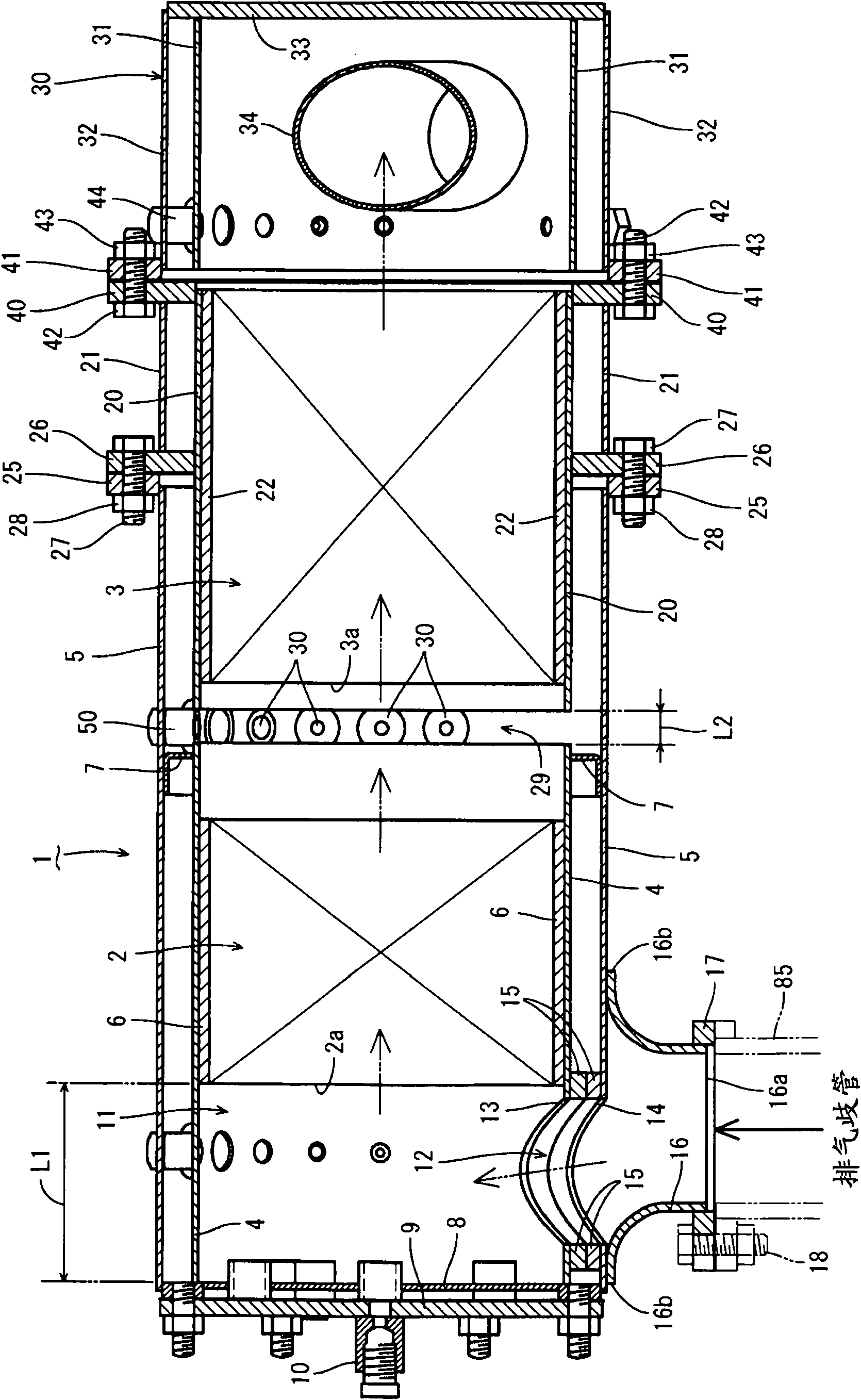
[0046] Hereinafter, embodiments embodying the present invention will be described with reference to the drawings. In addition, in the following description, the exhaust gas inflow side is simply referred to as the left side, and similarly, the exhaust gas discharge side is simply referred to as the right side.

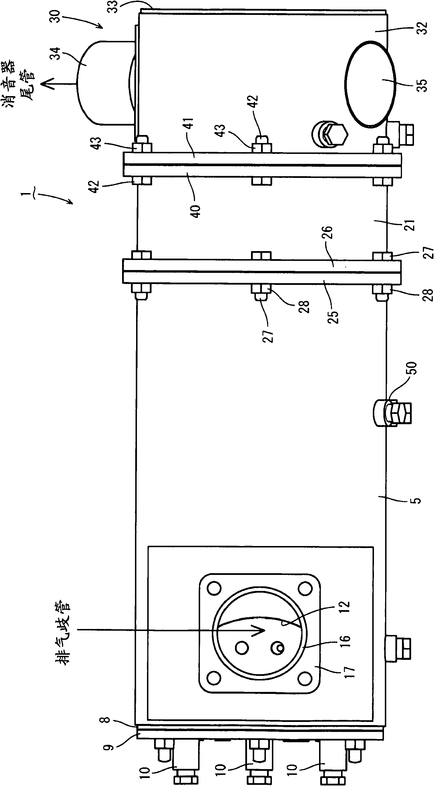
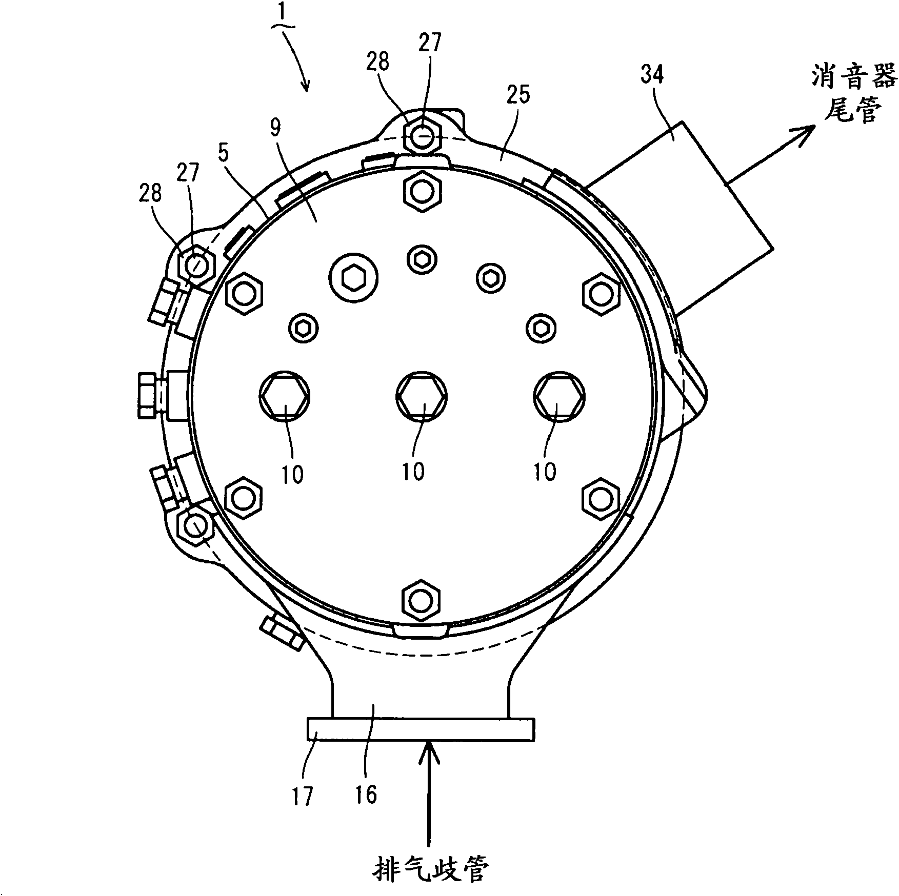
[0047] First, refer to Figure 1 to Figure 9 The overall structure of the exhaust gas purification device will be described. like Figure 1 to Figure 5 As shown in FIG. 1 , a continuously regenerative diesel particulate filter 1 (hereinafter, referred to as DPF) is provided as the exhaust gas purification device of the present embodiment. The DPF1 is used to physically trap particulate matter (PM) and the like in exhaust gas. DPF1 is in the direction of exhaust gas movement (from figure 1 Diesel oxidation catalyst 2 such as platinum that generates nitrogen dioxide (NO2) and a honeycomb structure soot filter that continuously oxidizes and removes captured particulat...


PUM


Abstract

The present invention aims to provide an engine device which allows a gas purifying filter (1) as a part constituting an engine (70) to be highly rigidly mounted to the engine (70), which eliminates the need that each device of a vehicle has countermeasures for exhaust gas, and which enhances the versatility of the engine (70). The engine device provided by the invention is provided with a diesel engine (70) having an exhaust manifold (71), and also with an exhaust gas purifying device (1) for purifying exhaust gas discharged by the diesel engine (70). Filter support bodies (19) for supporting the exhaust gas purifying device (1) are provided to the upper part of a flywheel housing (78) of the diesel engine (70). The exhaust gas purifying device (1) is connected to the exhaust manifold (71) and also connected to the flywheel housing (78) through the filter support bodies (19).

Description

technical field [0001] The present invention relates to an engine device for a working machine such as a backhoe, a forklift or a tractor, and more particularly, to a mounting structure of an exhaust gas purification device with respect to the engine. Background technique [0002] At present, in the exhaust path of a diesel engine, as an exhaust gas purification device (post-processing device), it is known to install a diesel particulate filter (or NOx catalyst), etc., and the exhaust gas discharged from the diesel engine is passed through the diesel particulate filter (or NOx catalyst). NOx catalyst) and the like to perform purification treatment (see Patent Document 1, Patent Document 2, and Patent Document 3). Also known is a technique in which a filter case (inner case) is provided in an outer case (outer case) and a particulate filter is arranged in the filter case (see Patent Document 4). [0003] Patent Document 1: Japanese Patent Laid-Open No. 2000-145430 [0004] ...

Claims


Application Information

Patent Timeline
Patent Type & Authority Applications(China)
IPC IPC(8): F02B67/00B60K13/04F01N13/08
CPCF01N2470/18F01N2013/023B60Y2200/15B60K13/04F01N2590/08F01N13/1805F01N2013/026B60Y2200/412F01N2470/02F01N3/0211F01N13/1894F01N13/1855F01N3/0335Y02T10/20F01N13/0093F01N13/0097F01N2340/04Y02T10/12E02F9/00F01N3/02
Inventor 光田匡孝小野寺恭志
Owner YANMAR POWER TECHNOLOGY CO LTD
Why Eureka
Try Eureka