Damping force adjustable shock absorber

A shock-absorbing force, adjustable technology, applied in the direction of shock absorbers, springs/shock absorbers, shock absorbers, etc., can solve the problems of difficult installation, limited shock absorber force, and reduced ride comfort, reducing the Cause of breakage, easy angle adjustment, effect of enhancing durability

Inactive Publication Date: 2011-08-24
KAN INNOVATION CONSTR
View PDF5 Cites 8 Cited by
  • Summary
  • Abstract
  • Description
  • Claims
  • Application Information

AI Technical Summary

Problems solved by technology

[0005] First, the damping is only done through the piston valve, so there are limitations to the control of the damping force
Moreover, the control device is exposed outside the shock absorber, so that the overall structure of the shock absorber is complicated and it is difficult to install in a narrow space
[0006] Second, the strength of the shock absorbing force used to reduce the external force has been set when the shock absorber first leaves the factory, so the shock absorber cannot be used instead of different car types
[0009] Fifth, if the shock absorber that cannot adjust the expansion force and compression force is installed on other vehicles, not only is it difficult to install, but also the difference in weight and shock absorption force will reduce the ride comfort, and the shock absorber will lose its basic function. Function

Method used


Image

  • Damping force adjustable shock absorber
  • Damping force adjustable shock absorber
  • Damping force adjustable shock absorber

Examples


Embodiment Construction

[0058] Hereinafter, preferred embodiments of the present invention will be described in detail with reference to the drawings. The terms and words used in this specification should not be limited to the usual or dictionary meanings. In order to explain their invention in the best way, the inventor can properly define the meaning of the terms. Meaning and implications of inventing technical ideas.

[0059] The embodiments recorded in this description and the composition of the drawings are only the most preferred embodiments of the present invention, and cannot fully represent the technical ideas of the present invention. Therefore, when applying, various equivalents and modified examples can be used. replace.

[0060] (constitute)

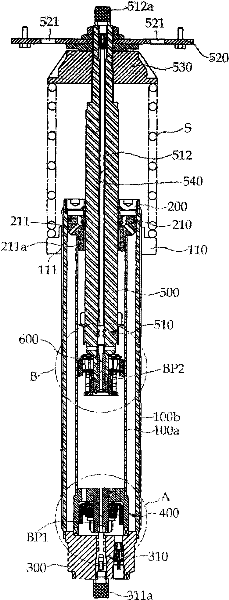
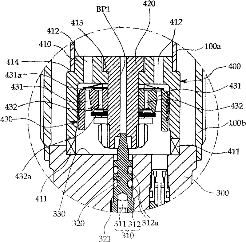
[0061] figure 1 It is a cross-sectional view illustrating the overall structure of the shock absorber of the present invention, figure 2 yes figure 1 Part A enlarged view in the figure is used to represent the state that the bottom valve of t...


PUM


Abstract

The invention provides a damping force-controllable shock absorber to be mounted on a vehicle regardless of the kind of the vehicle by adjusting the damping force according to the expansion and contraction of the shock absorber with features of outstanding control effect, simple structure and easy installation. The damping force-controllable shock absorber comprises: a cylinder casing having a double tube structure of an inner cylinder and an outer cylinder; an upper cap and a lower cap arranged on the two ends of the cylinder casing; a bottom valve body mounted on the lower cap, wherein a first passage is formed in the center of the bottom valve body and the damping force is adjusted by a compression damping force control means on the lower cap; a rod inserted into the upper cap while maintaining airtightness, wherein an end of the rod is extended into the inner cylinder and has a second bypass passage for connecting an upper chamber and a lower chamber, wherein a tensile strength adjustment means for adjusting a degree of opening and shutting of the second bypass passage is provided in a length direction; and a piston valve body disposed on an end of the rod, wherein the piston valve body faces the bottom valve body, wherein the piston valve body determines a flow direction of the working fluid between the upper chamber and the lower chamber when the rod is expanded and contracted.

Description

technical field [0001] The present invention relates to a shock absorber with adjustable damping force, and more specifically relates to a shock absorber that can adjust the compression force and tension regardless of the type of vehicle, can adjust the installation position according to the wheel camber angle, and can also adjust the height of the vehicle arbitrarily. Shock absorber with adjustable damping force that is tall, simple in structure and easy to install. Background technique [0002] Generally, shock absorbers are installed on the suspension of automobiles in order to improve ride quality and rotational force. The shock absorber prevents the spring from bouncing repeatedly due to the impact caused by the height difference of the road surface. [0003] The telescopic shock absorber that supplements the spring can be divided into an oil shock absorber that uses oil as the working fluid and a gas shock absorber that uses gas as the working fluid. The first to be ...

Claims


Application Information

Patent Timeline
Patent Type & Authority Applications(China)
IPC IPC(8): B60G17/08F16F9/18F16F9/32F16F9/44F16F9/34F16F9/54
CPCF16F9/44F16F9/466B60G17/08
Inventor 严泰雄
Owner KAN INNOVATION CONSTR
Why Eureka
Try Eureka