
Adaptive drive system of aortic blood pump position

A driving system and self-adaptive technology, applied in the field of biomedical engineering, can solve the problems of increasing the volume of foreign objects, increasing the rejection of the human body, and not being able to run continuously for a long time, so as to avoid infection and improve the quality of life

Inactive Publication Date: 2011-08-31
BEIJING UNIV OF TECH
View PDF6 Cites 9 Cited by
  • Summary
  • Abstract
  • Description
  • Claims
  • Application Information

AI Technical Summary

Problems solved by technology

But whether it is built-in battery energy storage or energy transmission through percutaneous wires, there are some disadvantages.
These disadvantages are mainly manifested in: for the built-in battery method, due to the limitation of current battery technology, it is impossible to provide energy for the blood pump system for a long time. Therefore, this type of system is only suitable for short-term assistance and cannot operate continuously for a long time; although the energy transfer method of percutaneous wire can solve the problem of continuous operation of the system, it is still difficult to solve the problem of continuous operation of the system because the wire will pass through the skin of the human body. , so it is extremely easy to cause infection and rejection, seriously affecting the quality of life of patients

Method used


Image

  • Adaptive drive system of aortic blood pump position
  • Adaptive drive system of aortic blood pump position
  • Adaptive drive system of aortic blood pump position

Examples


Embodiment Construction

[0012] An embodiment of the present invention will be specifically described below in conjunction with the accompanying drawings.

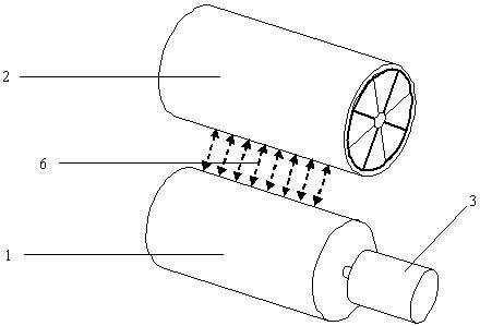
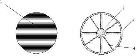
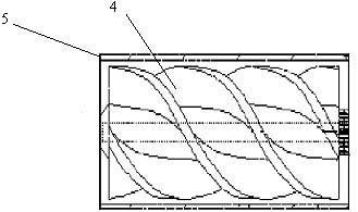
[0013] In the aortic position adaptive drive system of this embodiment, the external permanent magnet rotor 1 is a cylinder made of NdFeB N50 material, radially magnetized with four pairs of magnetic poles, with an outer diameter of 40 mm and a length of 40 mm. The main body 2 of the aortic blood pump has an outer diameter of 40 mm and a length of 40 mm. It is composed of a blood pump housing 5 and a helical permanent magnet impeller 4. The blood pump housing 5 is cylindrical with a shaft socket in the middle of the two ends. It is erected in the shaft socket; the impeller 4 is made of NdFeB N50 material, and 2 pairs of magnetic poles are radially magnetized.

[0014] The aortic blood pump body 2 is placed in the aorta, between the aortic root and the aortic arch, and the extracorporeal permanent magnet rotor 1 is placed outside the patient's ches...


PUM


Abstract

The utility model relates to an adaptive drive system of an aortic blood pump position, belonging to the field of biomedical engineering. The system consists of an in vitro permanent magnet rotor (1), a brushless motor (3) and an in vivo aortic blood pump body (2), wherein an in vitro permanent magnet is a radially magnetized cylindrical permanent magnet, and the aortic blood pump body consists of a blood pump housing and a radially magnetized impeller arranged in the blood pump housing; and the in vitro permanent magnet is driven by the in vitro brushless motor, and the in vitro permanent magnet rotor drives the aortic blood pump to rotate to supply blood to the human body because of the presence of magnetic coupling. The invention adopts the in vitro rotating magnetic field to directly supply kinetic energy to the blood pump without built-in batteries and transcutaneous leads, so that the risk of infection is avoided, and the quality of life of patients is improved. The system can adjust and ensure that the in vivo blood pump and the in vitro permanent magnet rotor are parallel or form a minimum angle, and the position of the in vivo blood pump can be adjusted by the in vitro permanent magnet rotor.

Description

technical field [0001] The invention relates to a position-adaptive drive device for an aortic blood pump, which belongs to the field of biomedical engineering. Background technique [0002] Blood pumps have gradually become one of the effective methods for treating heart failure, but in traditional blood pump systems, most of them use built-in batteries or percutaneous wires to transmit energy to the blood pump in the body. However, there are some disadvantages whether it is built-in battery energy storage or energy transmission through percutaneous wires. These disadvantages are mainly manifested in: for the built-in battery method, due to the limitation of current battery technology, it is impossible to provide energy for the blood pump system for a long time. Therefore, this type of system is only suitable for short-term assistance and cannot operate continuously for a long time; although the energy transfer method of percutaneous wire can solve the problem of continuou...

Claims


Application Information

Patent Timeline
Patent Type & Authority Applications(China)
IPC IPC(8): A61M1/12
Inventor 常宇高斌谷凯云刘有军乔爱科
Owner BEIJING UNIV OF TECH
Learn More