Electric control dual-chamber relay valve

A relay valve, electro-pneumatic technology, applied in the direction of control valves and air release valves, brake components, brakes, etc., can solve the problems of affecting the sensitivity of the piston, poor flexibility, and can not be completely eliminated, so as to achieve good pressure following sensitivity and pressure The effect of stability, reliable performance and simple structure

Active Publication Date: 2011-08-31
BEIJING CSR TIMES LOCOMOTIVE & ROLLING STOCK MECHANICS
View PDF5 Cites 22 Cited by
  • Summary
  • Abstract
  • Description
  • Claims
  • Application Information

AI Technical Summary

Problems solved by technology

[0009] Second, the relay valve is an important part of the electropneumatic brake control device. As an important part of the electropneumatic brake of the railway vehicle, it is required to have good pressure following sensitivity, and the diaphragm 1 of the above relay valve i

Method used


Image

  • Electric control dual-chamber relay valve
  • Electric control dual-chamber relay valve
  • Electric control dual-chamber relay valve

Examples


Example Embodiment

[0040] The core of the present invention is to provide an electro-pneumatic double-chamber relay valve with safe and reliable performance, high sensitivity, and relatively low manufacturing process difficulty and manufacturing cost.

[0041] In order to enable those skilled in the art to better understand the solution of the present invention, the present invention will be further described in detail below with reference to the accompanying drawings and specific embodiments.

[0042] The terms "up, down, left, and right" in this article are based on the positional relationship of the drawings, and should not be understood as an absolute limit to the scope of protection. The terms "first, second" and other terms are only for It is easy to describe to distinguish different components with the same name, and does not indicate a sequence or a primary-secondary relationship.

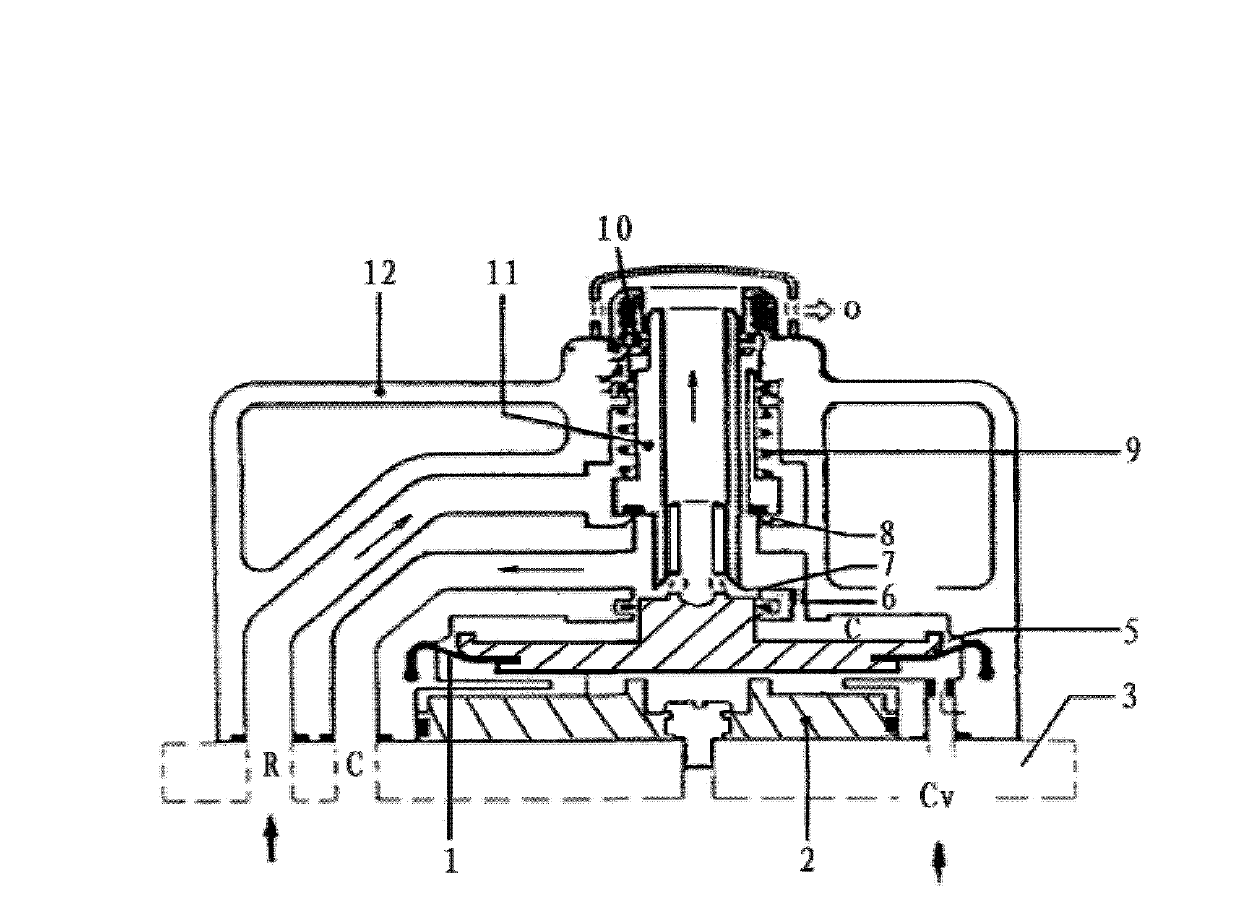
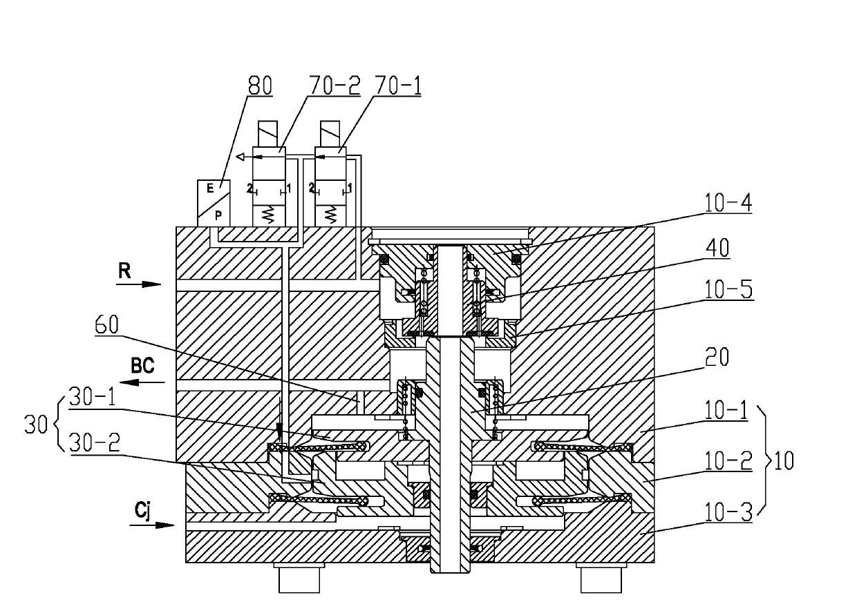
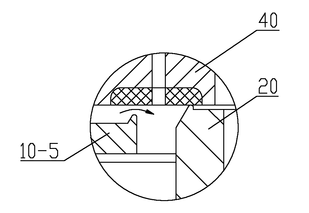
[0043] Please refer to figure 2 , figure 2 It is a schematic structural diagram of a specific embodiment of the...


PUM


Abstract

The invention discloses an electric control dual-chamber relay valve which comprises a valve body, a piston rod positioned in the valve body and a lifting valve controlled by up-and-down motion of the piston rod, wherein a total air inlet of the valve body and an outlet of a brake cylinder are respectively communicated with a total air cavity and a brake cylinder cavity which are arranged at the upper part of the lifting valve, a piston on the piston rod comprises an upper piston and a lower piston, an upper template is arranged between the upper piston and the valve body, a lower template isarranged between the lower piston and the valve body, a pressure feedback cavity formed above the upper template is communicated with the brake cylinder cavity through a throttling hole, a first control cavity formed between the upper template and the lower template is communicated with a common pre-control pressure air inlet of the valve body, and a second control cavity below the lower templateis communicated with an emergency pre-control pressure air inlet of the valve. The relay valve has the advantages of safe and reliable property, high sensitivity, relatively lower difficulty in manufacture process and relatively lower manufacture cost.

Description

Technical field [0001] The invention relates to the technical field of control valves, in particular to a relay valve that controls the charging and discharging of a train brake cylinder according to an air pressure command to realize the functions of braking, relief and pressure maintaining. Background technique [0002] The relay valve is an important pneumatic component in the electro-pneumatic brake control device of railway locomotives and rolling stock. During the braking process of the vehicle, the master controller or the train control vehicle-mounted device first sends out control commands such as train traction, idling, and braking, and passes The train connection or train network transmits the command signal. After receiving the command, the electronic control component in the electro-pneumatic brake control device of each vehicle calculates the braking force according to the vehicle weight and the principle of electric brake priority, and then calculates the required b...

Claims


Application Information

Patent Timeline
IPC IPC(8): B60T15/18
Inventor 潘兴河童毅张礼春陈洁
Owner BEIJING CSR TIMES LOCOMOTIVE & ROLLING STOCK MECHANICS
Why Eureka
Try Eureka