Ultra-high pressure fluid jetting power track transferring system and method for aircraft

A fluid jet and aircraft technology, applied in the field of aerospace vehicles, can solve the problems of consuming aircraft energy consumption, complicated design, difficult to operate, etc., and achieve the effects of low equipment cost, simple maintenance and strong penetration force.

Inactive Publication Date: 2011-08-31
洪瑞庆
View PDF4 Cites 16 Cited by
  • Summary
  • Abstract
  • Description
  • Claims
  • Application Information

AI Technical Summary

Problems solved by technology

[0005] The aerodynamic shape of an aircraft will determine its aerodynamic characteristics under a given gas flow state. Currently, the shapes of space shuttles, space shuttles, and aerospace aircraft have inherent design defects, which cause them to require more auxiliary equipment, Therefore, the design becomes more and more complicated, more and more difficult to operate, and more and more heavy, which makes the aircraft more and more energy-consuming, and there are a series of disadvantages such as
[0006] 1. The shape design of the space shuttle is a big failure in aerodynamics. Its shape is basically like a cigar-shaped metal rod. This aerodynamic shape cannot be helped by the lifting force of the air during flight. The space shuttle can only be lifted into the sky with the help of a high-thrust rocket, which requires a huge amount of energy to be consumed by it. This method is not desirable in the aerospace industry and will definitely be eliminated in the future.
[0007] 2. The sky plane also imitates the shape of the space shuttle, and its take-off mode is similar to that of the space shuttle. It just uses a large aircraft to send it to high altitude and then leaves the plane, and then turns on its own rocket engine to fly out of the atmosphere. Then the space shuttle’s The disadvantages are also fully reflected in it, and it will also be eliminated in the future
[0008] 3. The take-off of the aircraft is mainly achieved by the force generated by the two wings and the air. Since the contact surface between the wings of the aircraft and the air is very limited, the only way to increase the power of the engine is to make the aircraft take off. Accelerating the speed to make up for the lack of aircraft lift-off force, this is the congenital deficiency in the shape design of the aircraft, and the flaws in the shape design lead to additional huge energy loss
[0009] 4. During the flight, the aircraft is mainly moving in a straight line, and the actions of take-off, landing, and orbit change must be completed in an instant, so these flying devices are a burden to the aircraft most of the time, and they will consume the energy of the aircraft. a lot of energy consumption
[0010] 5. We know that things with more complex mechanical structures will have more negative interference with each other, and the probability of equipment damage will be higher; things with more complex mechanical structures will be more difficult to control, and the safety factor of the aircraft will decrease. Advanced equipment not only increases the difficulty of flying the aircraft, but also increases the cost of personnel training and maintenance.
[0011] 6. Because these orbit changing devices still cannot meet people's needs for aircraft, people have developed a kind of engine called "vector engine", the tail nozzle can rotate at a certain angle to help the aircraft improve maneuverability, but the effect is still not satisfactory. Satisfied
[0012] 7. The cost comparable to the investment of the aircraft is the construction of the airport and a series of supporting facilities such as personnel and equipment

Method used


Image

  • Ultra-high pressure fluid jetting power track transferring system and method for aircraft
  • Ultra-high pressure fluid jetting power track transferring system and method for aircraft
  • Ultra-high pressure fluid jetting power track transferring system and method for aircraft

Examples


Embodiment Construction

[0081] The present invention will be described in further detail below in conjunction with the accompanying drawings, and this manufacturing technique is very clear to those skilled in the art.

[0082] The invention is applied to civil and military aviation and aerospace fields.

[0083] Effects applied to modern aircraft:

[0084] (1) When the combined nozzle holes are used as the jet parts of the empennage or ventral fin on the military or civilian aircraft with empennage, the jet effect of the honeycomb geometry arrangement

[0085] see Figure 4 : On the opposite sides of the tail of the aircraft Figure 4 -d, the plane of symmetry above and below the tail Figure 4 -e is equipped with combined nozzles, each square hole represents a nozzle with combined nozzles, after programming, it can form ever-changing forms of jetting gas.

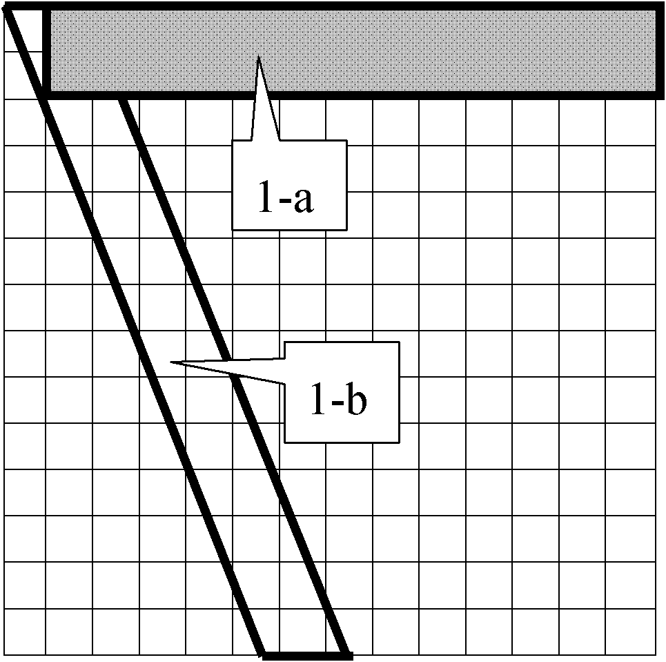
[0086] figure 1 For example: see 1-a when the combination of nozzle holes is opened, it forms a straight jet shape; see 1-b when the combin...


PUM


Abstract

The invention relates to the technical field of aviation and aerospace aircrafts, in particular to an ultra-high pressure fluid jetting power track transferring system and an ultra-high pressure fluid jetting power track transferring system method for an aircraft. The track transferring system is characterized by comprising combined jet holes which are geometrically arranged in a cellular form, and one or more gas pressure storage devices, wherein the combined jet holes are formed by geometrically arranging a plurality of nozzles in the cellular form, and are arranged on the flap, the aileron, the empennage, the canard or the ventral fin of the aircraft; each gas pressure storage device is supplied with gas by an engine, arranged inside the aircraft and connected with the combined jet holes by gas transferring pipelines; and downward jet pipes are arranged below the gas pressure storage devices. Compared with the prior art, the invention has the greatest advantages that: equipment has low cost and is convenient to operate and maintain, the aviation and aerospace cost is greatly lowered, a large-scale aerospace launching field with complex equipment or a large-scale airport runway is not required, and only one airport is required.

Description

[technical field] [0001] The invention relates to the technical field of aerospace vehicles, in particular to an ultra-high pressure fluid injection power orbit change system and method for aircraft. [Background technique] [0002] Moving objects, whether they are space shuttles, aircraft, rockets, missiles and other moving objects flying in the sky, or moving objects navigating on water or diving underwater, will be in contact with airflow during flight or navigation. Or in contact with the resistance of the water flow, it is necessary to change the direction of its movement, which we call "direction change track". The existing track change methods all use the swing of a mechanical device to make the horizontal air flow or the horizontal liquid flow The direction of motion of the moving object changes, forming another force, which is used to make the moving object complete the orbit change. [0003] The following are examples of existing technologies for various moving obj...

Claims


Application Information

Patent Timeline
Patent Type & Authority Applications(China)
IPC IPC(8): B64D27/18
CPCB64C9/38B64C15/14
Inventor 洪瑞庆
Owner 洪瑞庆
Why Eureka
Try Eureka