Device and method for measuring output liquid of coal bed methane well

A coalbed methane well and production fluid technology, which is applied in the directions of measurement, earthwork drilling, wellbore/well components, etc., can solve problems such as incomplete production fluid, liquid measurement accuracy, and inability to perform liquid measurement. And the effect of easy maintenance, wide market demand and good application prospects

Active Publication Date: 2011-08-31
潘军
View PDF7 Cites 6 Cited by
  • Summary
  • Abstract
  • Description
  • Claims
  • Application Information

AI Technical Summary

Problems solved by technology

No matter which flow form will greatly affect the speed of the impeller of the flowmeter due to the existence of gas, resulting in problems with the accuracy of liquid metering
[0005] 3. When the amount of produced liquid is small, it may occur that the produced liquid cannot fill the ground measuring pipe section equipped with the flow meter. At this time, although there is liquid flowing through, the impeller rotates slowly, resulting in accurate liquid measurement. degree of problems
If the liquid level is lower than the impeller of the flowmeter, the impeller will not rotate, and liquid metering cannot be performed at this time
[0006] The appearance of the above situations will not only affect the measurement accuracy of the liquid, but more importantly, the above three situations will easily lead people to misjudge the production status of the coalbed methane well, especially when the gas volume in the liquid is large or the liquid production rate is low. Larger errors in measurement accuracy lead to serious misjudgments of the production status of coalbed methane wells, which are prone to irreparable major economic losses

Method used


Image

  • Device and method for measuring output liquid of coal bed methane well
  • Device and method for measuring output liquid of coal bed methane well

Examples


Embodiment Construction

[0027] Below in conjunction with example the present invention is described in detail.

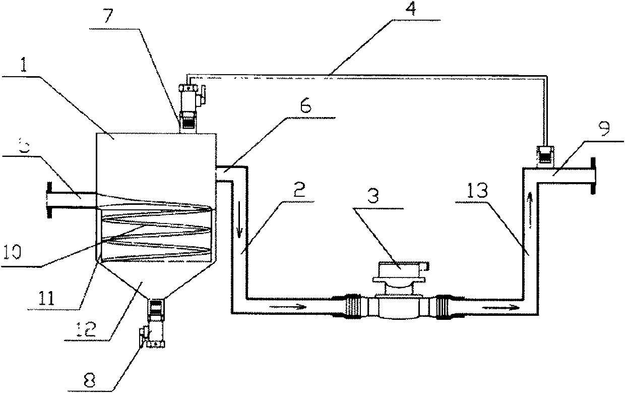
[0028] Such as figure 1As shown, the device for measuring the produced liquid of a coalbed methane well according to the present invention includes a buffer tank 1 , a liquid flow meter 3 , a first connecting pipe 2 and a second connecting pipe 13 . The buffer tank 1 is provided with a buffer tank inlet 5, a buffer tank liquid outlet 6, a gas outlet 7 and a solid phase outlet 8. The upper part of the buffer tank 1 is a cylinder, and the bottom is a cone 12. The inside of the buffer tank 1 A helical pipeline 10 is installed. One port of the flow meter 3 communicates with the liquid outlet 6 of the buffer tank through the first connecting pipe 2 , and the other port connects with the second connecting pipe 13 , and the other end of the second connecting pipe 13 is the measuring liquid outlet 9 . The first connecting pipe 2 , the liquid flowmeter 3 and the second connecting pipe 13 jointly ...


PUM


Abstract

The invention discloses a device and a method for measuring output liquid of a coal bed methane well. The device comprises a buffer vessel, a fluid flowmeter and a connecting pipe, wherein the buffer vessel is provided with an inlet and an output of output liquid, the top of the buffer vessel is provided with a gas outlet, and the bottom of the buffer vessel is provided with a solid phase outlet; the fluid flowmeter and the connecting pipe constitute a U-shaped pipeline, and the fluid flowmeter is at the bottom of the U-shaped pipeline; and two ends of an exhaust pipe are respectively connected with the gas outlet of the buffer vessel and the liquid outlet of the U-shaped pipeline. The method is as follows: after the output liquid of the coal bed methane well is separated by the buffer vessel, the output liquid passes through the flowmeter to be measured. The method enables the liquid to be separated from solid phase coal dust and gas prior to passing through the flowmeter, and only the liquid passes through the fluid flowmeter. Therefore, the measuring accuracy is improved. When the output liquid is small in amount, the physical principle of the U-shaped pipeline is used for improving the measuring accuracy. The measuring method is high in accuracy, can be used for metering the output liquid of the coal bed methane well, the output oil or water in an oil gas well or other similar working conditions.

Description

technical field [0001] The invention belongs to the field of liquid measurement, and in particular relates to a device and method for measuring the output liquid of a coal bed gas well. Background technique [0002] Although people know that the main component of the liquid produced by coalbed methane wells is water, and also contains a small amount of coal powder and gas, which have a great impact on the measurement accuracy of liquid, but the common liquid is still widely used in the field of coalbed methane wells. Flowmeter, the main problems of this measurement method are: [0003] 1. The pulverized coal will adhere to the impeller of the flowmeter, which will cause inaccurate measurement due to affecting the normal rotation of the impeller. [0004] 2. During the process of the gas being compressed in the formation and being discharged to the ground together with the liquid in the state of small bubbles, the pressure on the bubbles will continue to decrease as they flo...

Claims


Application Information

Patent Timeline
IPC IPC(8): E21B47/00E21B43/34E21B43/12
Inventor 潘军
Owner 潘军
Why Eureka
Try Eureka