Supercharge Your Innovation With Domain-Expert AI Agents!

Clock frequency detection circuit

A technology for detecting circuit and clock frequency, which is applied in the direction of frequency measurement device and frequency-to-amplitude conversion. Simple, low power, low cost effect

Active Publication Date: 2013-04-24
SHANGHAI BEILING
View PDF4 Cites 0 Cited by
  • Summary
  • Abstract
  • Description
  • Claims
  • Application Information

AI Technical Summary

Problems solved by technology

[0003] Because the commonly used clock frequency detection circuit is often composed of more complex, need counters, comparators, etc., which will consume more hardware resources and power consumption, not suitable for some low-cost applications, therefore, how to use less hardware and more Low power consumption to complete the frequency detection of the input clock is a technical problem that the industry needs to solve urgently

Method used


Image

  • Clock frequency detection circuit
  • Clock frequency detection circuit
  • Clock frequency detection circuit

Examples


Embodiment Construction

[0014] Specific embodiments of the present invention will be described in detail below in conjunction with the accompanying drawings.

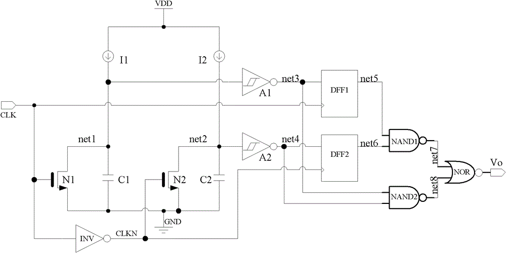
[0015] Such as figure 1 As shown, the present invention is a clock frequency detection circuit, which includes a first logic detection unit, a second logic detection unit and a logic operation unit.

[0016] The first logic detection unit includes a first Schmitt inverter A1, a first D flip-flop DFF1, a first switching tube N1, and a first current source I1 and a first capacitor sequentially connected in series between an external power supply VDD and ground C1, wherein the drain and the source of the first switching transistor N1 are respectively connected to both ends of the first capacitor C1, and the source of the first switching transistor C1 is grounded; the input end of the first Schmidt inverter A1 is connected to Between the first current source I1 and the first capacitor C1, its output terminal is connected to the input terminal of ...


PUM


Abstract

The utility model relates to a clock frequency detection circuit which comprises a first logical detection unit, a second logical detection unit and a logical operation unit. The first logical detection unit comprises a first Schmidt flipper, a first D trigger, a first current source and a first capacitance connected between an external power and the ground in series in sequence, and a first switching tube connected with two ends of the first capacitance in parallel; the second logical detection unit comprises a second Schmidt flipper, a second D trigger, a second current source and a second capacitance connected between the external power and the ground in series in sequence, and a second switching tube connected with two ends of the second capacitance in parallel. The clock frequency detection circuit not only can detect whether an input clock signal of the detection circuit exists or not, but also can detect the clock signal frequency inputted by the circuit satisfies preset requirements or not; therefore, the clock frequency detection circuit can be broadly applied to any circuit requiring clock detection, and particularly applied to a plurality of circuits or systems requiring low cost and low power consumption.

Description

technical field [0001] The invention relates to an integrated circuit, in particular to a clock frequency detection circuit. Background technique [0002] For most digital circuits and digital-analog hybrid circuits, it is often necessary to provide one or a group of clock signals with a certain frequency externally. The absence of the clock signal and the speed of the clock frequency often seriously affect the working state of the circuit, and may even lead to the paralysis of the circuit or the decline of the circuit performance. Therefore, it is necessary to detect the clock frequency in this type of circuit. [0003] Because the commonly used clock frequency detection circuit is often composed of more complex, need counters, comparators, etc., which will consume more hardware resources and power consumption, not suitable for some low-cost applications, therefore, how to use less hardware and more Low power consumption to complete the frequency detection of the input cl...

Claims


Application Information

Patent Timeline
Patent Type & Authority Patents(China)
IPC IPC(8): G01R23/06
Inventor 陶园林
Owner SHANGHAI BEILING
Features
  • R&D
  • Intellectual Property
  • Life Sciences
  • Materials
  • Tech Scout
  • Unparalleled Data Quality
  • Higher Quality Content
  • 60% Fewer Hallucinations
Learn More