Updip entrance double-layer tubular slug flow catcher
A slug flow and trap technology, which is used in pipeline systems, mechanical equipment, gas/liquid distribution and storage, etc., can solve the problems of no gas phase mist trapping, large floor space, and large liquid carrying capacity, reducing Liquid inlet and exhaust resistance, the effect of saving floor space
- Summary
- Abstract
- Description
- Claims
- Application Information
AI Technical Summary
Problems solved by technology
Method used
Image
Examples
specific Embodiment approach 1
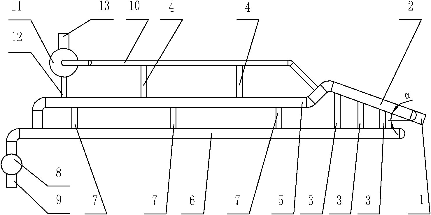
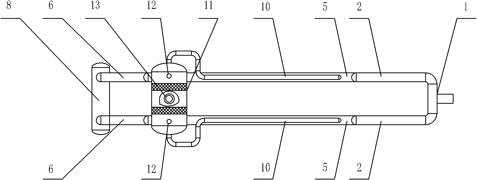
[0019] Specific implementation mode one: combine figure 1 and figure 2 Describe this embodiment, the double-layer tubular slug flow collector with an upward inclination inlet in this embodiment includes an inlet pipe 1, a liquid collection pipe 8, a liquid outlet 9, a two-way inlet mist catcher 11, a gas outlet 13, two upper The pouring pipe section 2, two upper layer pipe sections 5, two lower layer pipe sections 6, two gas collecting pipes 10, two liquid discharge pipes 12, a plurality of downcomer pipes 3, a plurality of air guide pipes 4 and a plurality of connecting pipes 7, the The two upper pipe sections 5 are arranged side by side horizontally, the two lower pipe sections 6 are arranged horizontally side by side, the two upper pipe sections 5 and the two lower pipe sections 6 are arranged side by side up and down, and the upper pipe sections 5 correspond to the lower pipe sections 6 up and down. , the head end of each upper layer pipe section 5 is connected with the ...
specific Embodiment approach 2
[0032] Specific implementation mode two: combination figure 1 To illustrate this embodiment, the tail of the incline pipe section 2 of this embodiment is bent downwards and communicates with the head end of the upper pipe section 5 . It is set in this way to prevent the liquid from flowing out of the tail end of the up-dipping pipe section, and backflow to the up-dipping pipe section (compared with the horizontal connection of the upper-layer pipe section at the end of the up-dipping pipe section) to reduce the gas-liquid separation efficiency, and use The gas-liquid laminar flow pattern makes the gas gather at a position higher than the top of the upper pipe section, which is conducive to gas discharge. Other compositions and connections are the same as in the first embodiment.
specific Embodiment approach 3
[0033] Specific implementation mode three: combination figure 1 To illustrate this embodiment, the tail of the upper pipe section 5 in this embodiment is bent vertically downwards and communicates with the tail of the corresponding lower pipe section 6 . The liquid phase flows into the lower pipe section 6 under the action of gravity. Other compositions and connections are the same as those in Embodiment 1 or Embodiment 2.
PUM
| Property | Measurement | Unit |
|---|---|---|
| Inclination | aaaaa | aaaaa |
Abstract
Description
Claims
Application Information
 - R&D
- Intellectual Property
- Life Sciences
- Materials
- Tech Scout
- Unparalleled Data Quality
- Higher Quality Content
- 60% Fewer Hallucinations
Browse by: Latest US Patents, China's latest patents, Technical Efficacy Thesaurus, Application Domain, Technology Topic, Popular Technical Reports.
© 2025 PatSnap. All rights reserved.Legal|Privacy policy|Modern Slavery Act Transparency Statement|Sitemap|About US| Contact US: help@patsnap.com


