Updip entrance double-layer tubular slug flow catcher

A slug flow and trap technology, which is used in pipeline systems, mechanical equipment, gas/liquid distribution and storage, etc. The problem of large liquid carrying capacity can achieve the effect of saving floor space, reducing liquid inlet and exhaust resistance, and smooth liquid inlet.

Active Publication Date: 2013-09-25
DAQING OILFIELD CO LTD +2
View PDF2 Cites 0 Cited by
  • Summary
  • Abstract
  • Description
  • Claims
  • Application Information

AI Technical Summary

Problems solved by technology

[0008] The purpose of the present invention is to solve the problem that the existing single-layer finger-shaped tubular slug catcher has large floor space, large liquid carrying capacity in gas, no gas-phase mist trapping function and the inability of the multi-branch trap at the inlet of the separator. The problem of capturing large volume liquid plugs, and then providing a double-layer tube type slug flow catcher with an upward inclination inlet

Method used


Image

  • Updip entrance double-layer tubular slug flow catcher
  • Updip entrance double-layer tubular slug flow catcher
  • Updip entrance double-layer tubular slug flow catcher

Examples


specific Embodiment approach 1

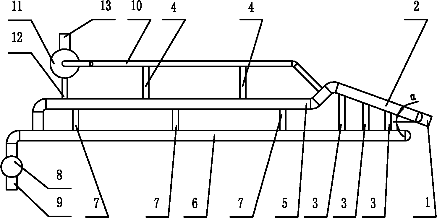
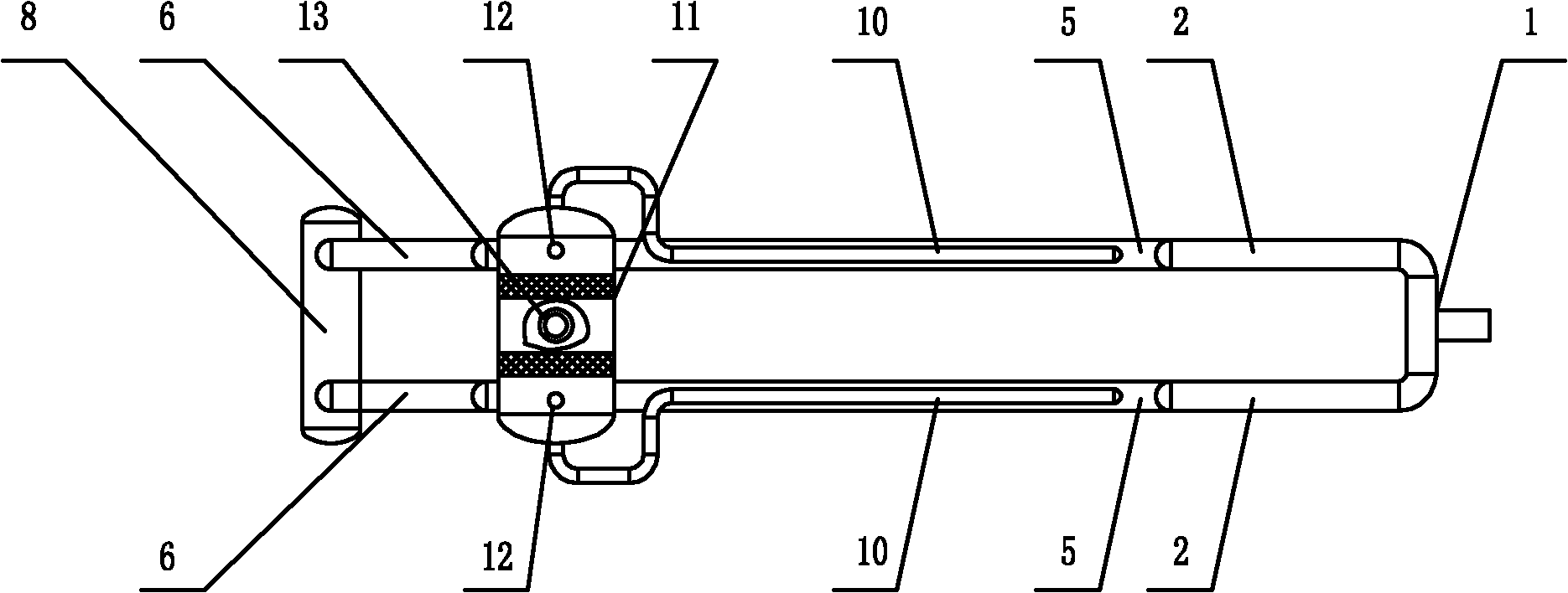
[0020] Specific implementation mode one: combine figure 1 and figure 2Describe this embodiment, the double-layer tubular slug flow collector with an upward inclination inlet in this embodiment includes an inlet pipe 1, a liquid collection pipe 8, a liquid outlet 9, a two-way inlet mist catcher 11, a gas outlet 13, two upper The pouring pipe section 2, two upper layer pipe sections 5, two lower layer pipe sections 6, two gas collecting pipes 10, two liquid discharge pipes 12, a plurality of downcomer pipes 3, a plurality of air guide pipes 4 and a plurality of connecting pipes 7, the The two upper pipe sections 5 are arranged side by side horizontally, the two lower pipe sections 6 are arranged horizontally side by side, the two upper pipe sections 5 and the two lower pipe sections 6 are arranged side by side up and down, and the upper pipe sections 5 correspond to the lower pipe sections 6 up and down. , the head end of each upper layer pipe section 5 is connected with the e...

specific Embodiment approach 2

[0033] Specific implementation mode two: combination figure 1 To illustrate this embodiment, the tail of the incline pipe section 2 of this embodiment is bent downwards and communicates with the head end of the upper pipe section 5 . It is set in this way to prevent the liquid from flowing out of the tail end of the up-dipping pipe section, and backflow to the up-dipping pipe section (compared with the horizontal connection of the upper-layer pipe section at the end of the up-dipping pipe section) to reduce the gas-liquid separation efficiency, and use The gas-liquid laminar flow pattern makes the gas gather at a position higher than the top of the upper pipe section, which is conducive to gas discharge. Other compositions and connections are the same as in the first embodiment.

specific Embodiment approach 3

[0034] Specific implementation mode three: combination figure 1 To illustrate this embodiment, the tail of the upper pipe section 5 in this embodiment is bent vertically downwards and communicates with the tail of the corresponding lower pipe section 6 . The liquid phase flows into the lower pipe section 6 under the action of gravity. Other compositions and connections are the same as those in Embodiment 1 or Embodiment 2.


PUM


Abstract

The invention relates to an updip entrance double-layer tubular slug flow catcher, and relates to a slug flow catcher, aiming to solve the problems of large floor space, large liquid carrying amount in gas and no gas phase fog catching function for the existing finger-type tubular slug flow catcher. Two upper-layer pipe sections and two lower-layer pipe sections are all horizontally arranged in parallel; the head end of each upper-layer pipe section is communicated with the tail end of an updip pipe section; the head end of the updip pipe section is communicated with an inlet pipe; the tail end of each upper-layer pipe section is communicated with the tail part of each lower-layer pipe section; the tail end of each lower layer pipe section is communicated with a liquid collecting pipe; two gas collecting pipes are horizontally arranged in parallel; the head end of the gas collecting pipe is communicated with the tail of the updip pipe section; the tail end of the gas collecting pipe is communicated with a bidirectional inlet fog catching device; the gas collecting pipe is communicated with the upper pipe section through a gas guide pipe; the upper-layer pipe sections are communicated with the lower-layer pipe sections through communicating pipes; the updip pipe section is communicated with the lower-layer pipe section through a downspout; and the bidirectional inlet fog catching device is communicated with the tail of each upper-layer pipe section through a liquid discharge pipe. The slug flow catcher provided by the invention is used for oil gas treatment of oil gas field surface engineering.

Description

technical field [0001] The invention relates to a slug flow catcher, in particular to a double-layer pipe type slug flow catcher with an upwardly inclined inlet, which belongs to the technical field of oil and gas treatment equipment for surface engineering in oil and gas fields. Background technique [0002] The slug flow catcher is an important equipment in the field of oil and gas gathering and transportation in oil and gas fields. It is installed at the end of long-distance oil and gas mixed transportation pipelines in oil and gas fields. In normal working condition, the gas supply to the downstream is not interrupted. There are mainly two types of slug flow traps used at home and abroad. One is the container type, which is an oil-gas separator structure and is mainly suitable for medium and low pressure conditions, small-length liquid slugs and offshore oil and gas production platforms with limited sites. occasions; the other finger-shaped tubular structure is a side-b...

Claims


Application Information

Patent Timeline
Patent Type & Authority Patents(China)
IPC IPC(8): F17D5/00F17D3/01
Inventor 宋承毅赵波王庆生张延松王桂秋
Owner DAQING OILFIELD CO LTD
Why Eureka
Try Eureka