Dynamic load test bed for shaft coupler

A technology of couplings and test benches, which is applied in the testing of machine gears/transmission mechanisms, etc., can solve problems such as high cost and affecting the normal operation of couplings, and achieve the effect of reducing test costs

Inactive Publication Date: 2011-09-07
ANHUI UNIVERSITY OF TECHNOLOGY
View PDF7 Cites 9 Cited by
  • Summary
  • Abstract
  • Description
  • Claims
  • Application Information

AI Technical Summary

Problems solved by technology

The use of the coupling is an open operation, that is, all the power provided by the motor must be consumed. Due to the high cost, the dynamic load test of the coupling can only be carried out on a sin

Method used


Image

  • Dynamic load test bed for shaft coupler
  • Dynamic load test bed for shaft coupler
  • Dynamic load test bed for shaft coupler

Examples


Embodiment Construction

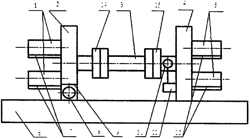
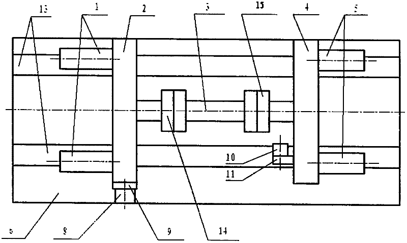
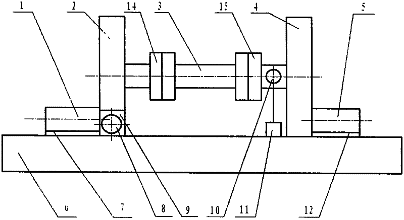
[0012] Further describe the technical scheme of the present invention below in conjunction with accompanying drawing: Figure 1~4 , The coupling dynamic load test bench includes, load motor 1, output reducer 2, tested coupling 3, input reducer 4, motor 5, equipment base 6, pressure sensor 7, travel motor 8, travel mechanism 9, The rotational speed sensor 10, the rotational speed sensor mounting bracket 11, the pressure sensor 12, the moving auxiliary slide rail 13, the output flange 14, and the input flange 15.

[0013] The output reducer 2 is connected to the equipment base 6 through the running mechanism 9, the output end of the output reducer 2 is mechanically connected to the load motor 1, and the input reducer 4 is connected to the equipment base 6 Mechanically connected, the input end of the input reducer 4 is mechanically connected to the motor 5 , and the traveling mechanism 9 is mechanically connected to the traveling motor 8 .

[0014] The input end of the output re...


PUM


Abstract

The invention provides a dynamic load test bed for a shaft coupler, which comprises a load motor, an output reducer, a shaft coupler to be tested, an input reducer, an electric motor, an equipment base, a pressure sensor, a traveling motor, a traveling mechanism, a revolution speed sensor, an installing bracket of the revolution speed sensor, another pressure sensor, a slide rail of a translating pair, an output flange and an input flange. The revolution speed sensor and the another pressure sensor are linked with a data acquisition device; and the conditions of working, wearing and damaging of components of the shaft coupler under different revolution speeds and torques can be obtained by processing and analyzing the acquired data. The dynamic load test bed for the shaft coupler provided by the invention is mainly used for overall integrated dynamic load test of the shaft coupler; the conditions of working, wearing and damaging of components of the shaft coupler under different revolution speeds and torques can be obtained by simulating the actual working conditions through the dynamic load test bed for the shaft coupler; in addition, the dump energy is recycled to the power grid after the test, thus the test cost is lowered.

Description

Technical field: [0001] The invention relates to a dynamic load test bench for rotating mechanical components, in particular to a dynamic load test bench for shaft couplings. Background technique: [0002] At present, the test and detection of the whole coupling are basically static. In particular, the entire coupling has not been subjected to a dynamic load test before leaving the factory, because the relevant national standard is a static test. Static test and dynamic load test are two different concepts. The static test cannot reflect the condition of the coupling in operation, and the dynamic load test is to build a motion platform to test the coupling according to the condition of the coupling in operation. The use of the coupling is an open operation, that is, all the power provided by the motor must be consumed. Due to the high cost, the dynamic load test of the coupling can only be carried out on a single component on the coupling. The current whole test of the co...

Claims


Application Information

Patent Timeline
IPC IPC(8): G01M13/02
Inventor 伍毅赵越晏群
Owner ANHUI UNIVERSITY OF TECHNOLOGY
Why Eureka
Try Eureka