
Test method for simulating working mechanism of drilling rig for gas drilling

A technology of gas drilling and test method, which is applied in the direction of testing wear resistance, testing machinability, etc., which can solve the problem of inability to test the fatigue life of drilling tools, restrict the large-scale application of gas drilling technology, and simulate the erosion and wear of drilling tools at the same time and other problems, to achieve the effect of quick start, light weight and quick response

Inactive Publication Date: 2011-09-07
SOUTHWEST PETROLEUM UNIV
View PDF3 Cites 13 Cited by
  • Summary
  • Abstract
  • Description
  • Claims
  • Application Information

AI Technical Summary

Problems solved by technology

However, the failure frequency of drilling tools in gas drilling is much higher than that in drilling fluid drilling, and the frequent occurrence of drilling tool failure accidents seriously restricts the large-scale application of gas drilling technology
At present, the theoretical analysis and experimental research on the failure of gas drilling tools have achieved preliminary results. The known test methods for gas drilling tools can only simulate the erosion and wear of cuttings on drilling tools during gas drilling, or can only simply simulate gas Drilling tools are subjected to a single force, but it is impossible to simultaneously simulate the force conditions of drilling tools erosion wear and lateral, longitudinal and torsional vibration in the gas drilling process, and it is also impossible to test the fatigue life of drilling tools

Method used


Image

  • Test method for simulating working mechanism of drilling rig for gas drilling
  • Test method for simulating working mechanism of drilling rig for gas drilling
  • Test method for simulating working mechanism of drilling rig for gas drilling

Examples


Embodiment Construction

[0015] The concrete implementation steps of the present invention are described below in conjunction with accompanying drawing:

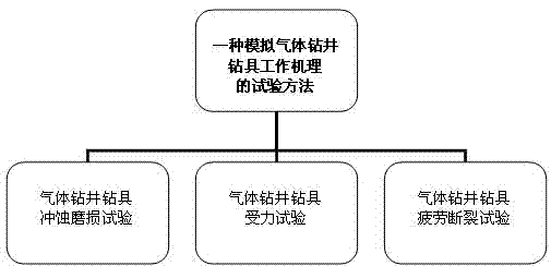
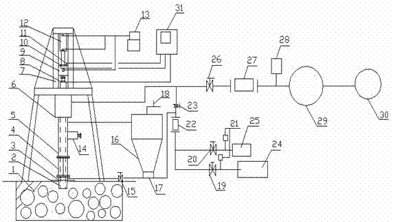
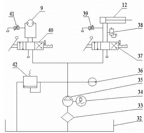
[0016] Such as figure 1 , figure 2 , image 3 As shown, the present invention is a kind of test method for simulating the working mechanism of gas drilling tools, including gas drilling tools erosion wear test method, gas drilling tool stress test method and gas drilling tool fatigue fracture test method.

[0017] The gas drilling drilling tool erosion wear test method adopts the following steps: ① before the test, the test derrick 7 is fixed on the cement foundation 1, and the weight of the drilling tool 2 in the test section before the test is weighed; ② the large fan 24 is turned on, and the small fan 25 and air compressor 29, through the pressure transmitter 21, flow sensor 22, pressure transmitter 28, and flow transmitter 27 to control the air pressure and air volume required for the test, and record the time when the fan is turned on at the...


PUM


Abstract

The invention relates to a test method for simulating a working mechanism of a drilling rig for gas drilling, and the method is used in the field of petroleum and gas drilling. The method comprises an erosion abrasion test method for the drilling rig for gas drilling, a force-bearing test method for the drilling rig for gas drilling and a fatigue fracture test method for the drilling rig for gas drilling, wherein the erosion abrasion test method for the drilling rig for gas drilling comprises the following steps: 1) before testing, fixing a testing derrick on a cement foundation and weighting out the weight of the drilling rig on a test section before testing; 2) starting different combinations of fans and then adjusting and controlling the air pressure and air quantity required by the test; 3) stopping blowing after testing for a period of time and recording the delta 2 at the moment; and 4) taking out the drilling rig on the test section and then weighting the drilling rig, thereby acquiring the abrasion loss of the drilling rig on the test section within unit time. The invention provides a convenient test method for researching the related problems of the working mechanism of the drilling rig for gas drilling in the gas drilling process, such as erosion abrasion, force-bearing and fatigue fracture failure of the drilling rig for gas drilling, and the like.

Description

technical field [0001] The invention relates to a test method for simulating the working mechanism of a gas drilling tool used in oil and gas drilling, and belongs to the technical field of oil and gas drilling technology. Background technique [0002] At present, due to its own advantages, gas drilling can effectively increase the mechanical penetration rate, effectively protect oil and gas layers, facilitate well deviation control, and overcome lost circulation, etc., and has very obvious economic and social benefits. Therefore, gas drilling technology is increasingly becoming one of the most effective technologies for oil and gas exploration and development in my country. However, the failure frequency of drilling tools in gas drilling is much higher than that in drilling fluid drilling, and the frequent occurrence of drilling tool failure accidents seriously restricts the large-scale application of gas drilling technology. At present, the theoretical analysis and experi...

Claims


Application Information

Patent Timeline
IPC IPC(8): G01N3/56G01N3/58
Inventor 黄志强陈次昌王钱钱李东洋张万福张涛
Owner SOUTHWEST PETROLEUM UNIV
Learn More