Method for performing space registration on radar and infrared sensor configured on identical platform
What is AI technical title?
AI technical title is built by Patsnap AI team. It summarizes the technical point description of the patent document.
An infrared sensor and spatial registration technology, applied in the field of data fusion, can solve problems such as inconsistent coordinate systems, low registration accuracy, and sensitive initial value of the system state
Inactive Publication Date: 2013-07-03
SHENZHEN UNIV
View PDF2 Cites 0 Cited by
Summary
Abstract
Description
Claims
Application Information
AI Technical Summary
This helps you quickly interpret patents by identifying the three key elements:
Problems solved by technology
Method used
Benefits of technology
Problems solved by technology
[0007] The purpose of the embodiments of the present invention is to provide a method for spatial registration of radar and infrared sensors configured on the same platform, aiming to solve the inconsistency between the target state and the actual demand coordinate system of the spatial registrationalgorithm of radar and infrared sensors provided by the prior art , the existing spatial registration algorithm is sensitive to the initial value of the system state, has restrictions on the initial value of the prediction covariance matrix, and the registration accuracy is relatively low
Method used
Image
Click on the blue label to locate the original text in one second.
Reading with bidirectional positioning of images and text.
Examples
Embodiment 1
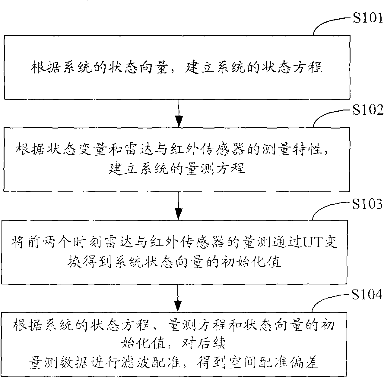
[0070] figure 1 It shows the implementation flow of the method for spatial registration of the radar and the infrared sensor configured on the same platform provided by the embodiment of the present invention, and the specific steps are as follows:
[0071] In step S101, according to the state vector of the system, the state equation of the system is established, namely:
[0072] X(t k+1 )=[h 1 (t k ), h 2 (t k ), h 3 (t k ), h 4 (t k ), h 5 (t k ), h 6 (t k ), h 7 (t k ), h 8 (t k )] T +W(t k ),in:
[0073] h 1 ( t k ) = sqrt ( ( ξ x ( t k ) + x ...
Embodiment 2
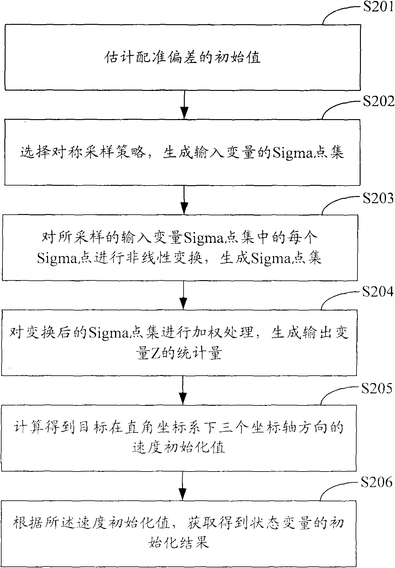
[0098] figure 2 It shows the implementation process of obtaining the initialization value of the system state vector through the UT transformation of the measurement of the radar and the infrared sensor at the first two moments provided by the embodiment of the present invention, and the specific steps are as follows:
[0099] In step S201, an initial value of registration deviation is estimated.
[0100] In the embodiment of the present invention, assume that the first two measurement data of the radar are respectively: (ρ r (t 0 ), θ r (t 0 ), η r (t 0 )), (ρ r (t 1 ), θ r (t 1 ), η r (t 1 )), the first two data of the infrared sensor are: (θ i (t 0 ), η i (t 0 )), (θ i (t 1 ), η i (t 1 )), so that the azimuth angle deviation and the elevation angle deviation of the infrared sensor are (Δθ i (t k ), Δη i (t k )), [ r ( t k ) ...
Embodiment 3
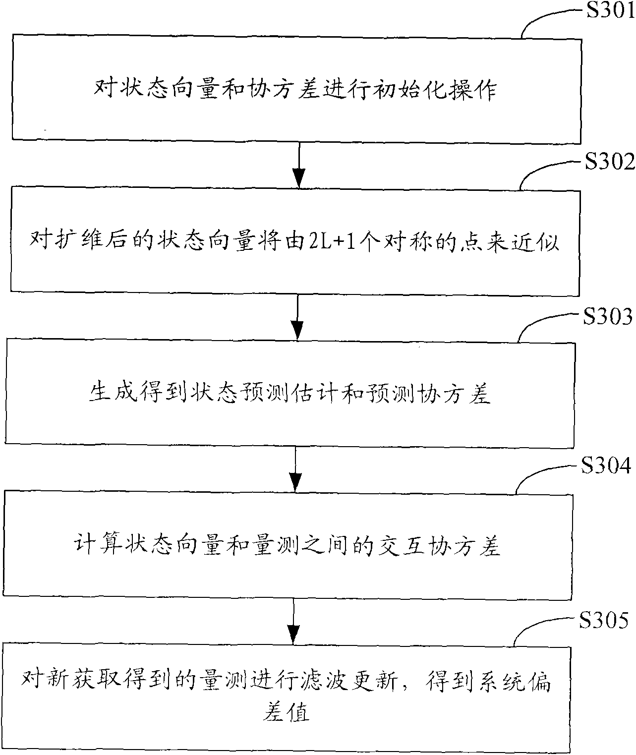
[0131] image 3 It shows the implementation process of performing UKF filter registration on the measurement data according to the initialization value of the state equation, measurement equation and state vector of the system provided by the embodiment of the present invention, and obtaining the spatial registration deviation of the infrared sensor relative to the radar, The specific steps are as follows:
[0132] In step S301, the state vector and covariance are initialized, namely:
[0133] x ^ 1 ( 0 ) = X ( t 0 ) = [ ρ r ( t 0 ) , θ ...
PUM
Abstract
The invention is applied in the technical field of data fusion, and provides a method for performing space registration on a radar and an infrared sensor configured on an identical platform. The method comprises the following steps of: establishing a system state equation and a measurement equation taking polar coordinate positions, rectangular coordinate velocity and polar coordinate registration deviations as state vectors; performing unscented transform (UT) on the measurement, performed at previous moments, of the radar and the infrared sensor to obtain initial values of the system state vectors; and performing unscented Kalman filtering (UKF) registration on measured data according to the system state equation, the measurement equation and the initial values of the state vectors to obtain the space registration deviation of the infrared sensor relative to the radar. By the method, limitations to the conventional space registration of the radar and the infrared sensor are avoided,and registration accuracy is improved.
Description
technical field [0001] The invention belongs to the technical field of data fusion, and in particular relates to a method for spatial registration of radars and infrared sensors configured on the same platform. Background technique [0002] With the development of science and technology, the performance of sensors has been greatly improved, and various multi-sensor systems facing complex application backgrounds have emerged in large numbers. Especially after entering the 1970s, a large number of high-tech weapons, especially precision-guided weapons and long-range strike weapons, appeared, expanding the scope of the battlefield to the five-dimensional space of sea, land, air, sky and electromagnetic. Relying on a single sensor to provide information can no longer meet the needs, and the use of data fusion technology to process observation data from active and passive detectors covering a wide frequency band such as microwave, millimeter wave, television, infrared, laser and ...
Claims
Application Information
Patent Timeline
Application Date:The date an application was filed.
Publication Date:The date a patent or application was officially published.
First Publication Date:The earliest publication date of a patent with the same application number.
Issue Date:Publication date of the patent grant document.
PCT Entry Date:The Entry date of PCT National Phase.
Estimated Expiry Date:The statutory expiry date of a patent right according to the Patent Law, and it is the longest term of protection that the patent right can achieve without the termination of the patent right due to other reasons(Term extension factor has been taken into account ).
Invalid Date:Actual expiry date is based on effective date or publication date of legal transaction data of invalid patent.

