
Pull rope electronic parking brake transmission mechanism

An electronic parking brake and transmission system technology, applied in the direction of mechanical brake transmission, etc., can solve the problems of increasing the labor intensity of the driver, affecting the space of the cab, and the long layout of the handbrake cable, so as to reduce the difficulty of starting on the slope , reduce the overall volume, improve the effect of convenience and safety

Active Publication Date: 2014-06-25
WANXIANGQIANCHAO CO LTD +1
View PDF6 Cites 3 Cited by
  • Summary
  • Abstract
  • Description
  • Claims
  • Application Information

AI Technical Summary

Problems solved by technology

[0002] At present, the parking brake of most cars mostly adopts the handbrake type parking brake, and its disadvantages are: (1) The handbrake needs to be pulled after parking, which increases the labor intensity of the driver, especially for female drivers. (2) When starting on a slope, it is necessary to rely on the driver to operate the hand brake, accelerator, and clutch correctly at the same time to start smoothly, which increases the difficulty of driving; (3) When parking on a slope, if If the handbrake is not in place, the car may drive backwards on the slope, causing an accident; (4) The handbrake operating handle affects the cab space, and the handbrake cable is relatively long, making it difficult to arrange

Method used


Image

  • Pull rope electronic parking brake transmission mechanism
  • Pull rope electronic parking brake transmission mechanism
  • Pull rope electronic parking brake transmission mechanism

Examples


Embodiment

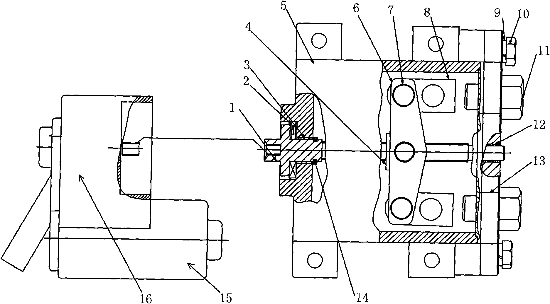
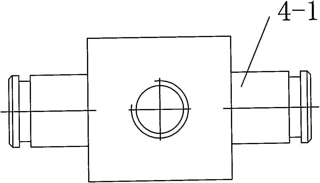
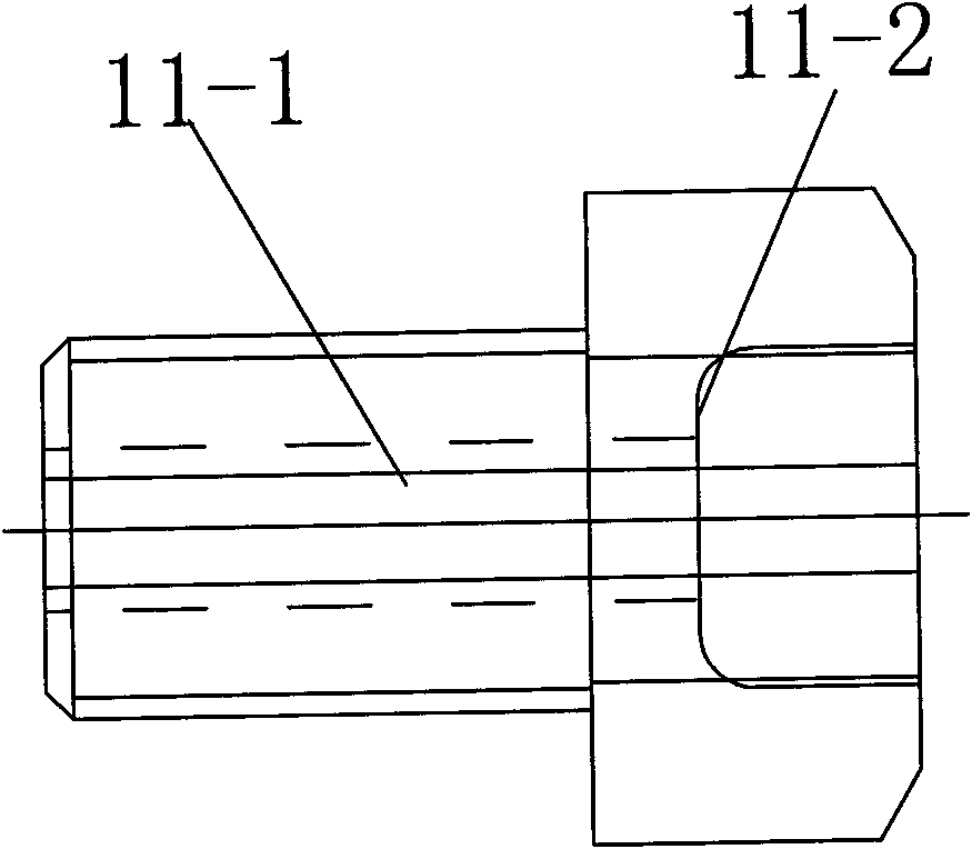
[0014] Example: such as figure 1 , the transmission system of this cable-type electronic parking brake is composed of a motor 15, a reduction mechanism 16 and a transmission mechanism. Fixed, the screw 1 is connected with the external spline of the output end of the reduction mechanism through the inner spline of the outer end, and is supported by the sliding bearing I3 and the sliding bearing II12 on the housing 5 hole and the end cover 13 hole respectively, and at the same time by the thrust roller bearing 2 and circlip 14 to axially locate it, the screw rod 1 and the square nut 4 cooperate through thread transmission, the cylindrical boss 4-1 on the square nut 4 cooperates with the middle hole of the balance arm 6, and the two balance arms 6 pass through the two Two connecting pin shafts 7 are connected, and two stay wire clips 8 are connected with the connecting pin shaft 7 by hole shaft cooperation, and the end cover 13 is also provided with a backguy adjustment nut 11 co...


PUM


Abstract

The invention relates to a pull rope electronic parking brake transmission system. The mechanism consists of a motor, a speed reducing mechanism and a transmission mechanism, wherein the transmission mechanism comprises a shell; an end cover is fixed with the shell through a connecting screw and a spring washer; a screw is connected with an internal spline at the output end of the speed reducing mechanism through an internal spline at an outer end, is respectively supported on a shell hole and an end cover hole through a sliding bearing I and a sliding bearing II, and is axially positioned by a thrust roller bearing and a clamping spring; the screw is in transmission fit with a square nut through threads; a cylindrical boss on the square nut is matched with middle holes of balance arms; the two balance arms are connected through two connecting pin shafts; two pull wire clips are connected with the connecting pin shafts through hole shaft fit; and the end cover is provided with pull wire adjusting nuts which correspond to the pull wire clips and are matched through pull wires. The mechanism has the advantages that: electricity is used for replacing mechanical operation, and quicker and lighter parking brake is provided; the motor is easily controlled automatically; ramp starting difficulty is reduced, and driving convenience and driving safety are improved; and the total volume of a parking operation part is reduced, and the mechanism is convenient to install.

Description

technical field [0001] The invention relates to a parking brake, in particular to a transmission system of a cable type electronic parking brake. Background technique [0002] At present, the parking brake of most cars mostly adopts the handbrake type parking brake, and its disadvantages are: (1) The handbrake needs to be pulled after parking, which increases the labor intensity of the driver, especially for female drivers. (2) When starting on a slope, it is necessary to rely on the driver to operate the hand brake, accelerator, and clutch correctly at the same time to start smoothly, which increases the difficulty of driving; (3) When parking on a slope, if If the handbrake is not in place, the car may drive backwards on the slope, causing an accident; (4) The handbrake operating handle affects the cab space, and the handbrake cable is relatively long and difficult to arrange. Contents of the invention [0003] The present invention aims to solve the above-mentioned sho...

Claims


Application Information

Patent Timeline
Patent Type & Authority Patents(China)
IPC IPC(8): B60T11/04
Inventor 资小林张杰郭增均邱宝象潘劲
Owner WANXIANGQIANCHAO CO LTD
Learn More