

Experimental test device for simulating internal heat transfer mechanism of multi-layer protective clothes
A test device and heat transfer technology, applied in the direction of thermal conductivity of materials, etc., can solve the problems such as the inability to simulate the heat transfer of protective clothing, the inability to consider the continuous sweating of the human body, and the inability to accurately measure the temperature of protective clothing, etc., to achieve repeatable operation, The effect of stable working performance and reasonable device structure
- Summary
- Abstract
- Description
- Claims
- Application Information
AI Technical Summary
Problems solved by technology
Method used
Image

Examples
Embodiment 1
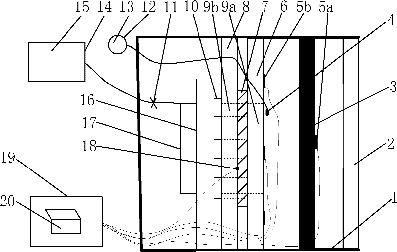
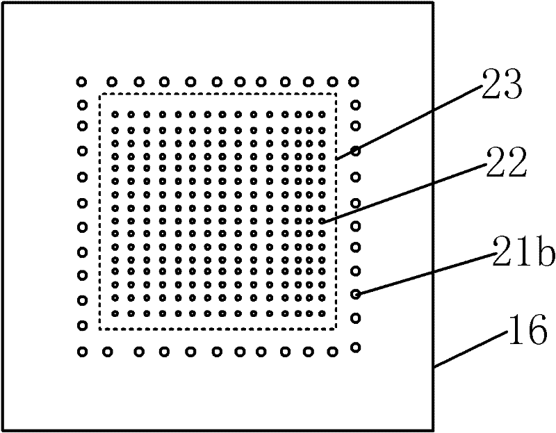
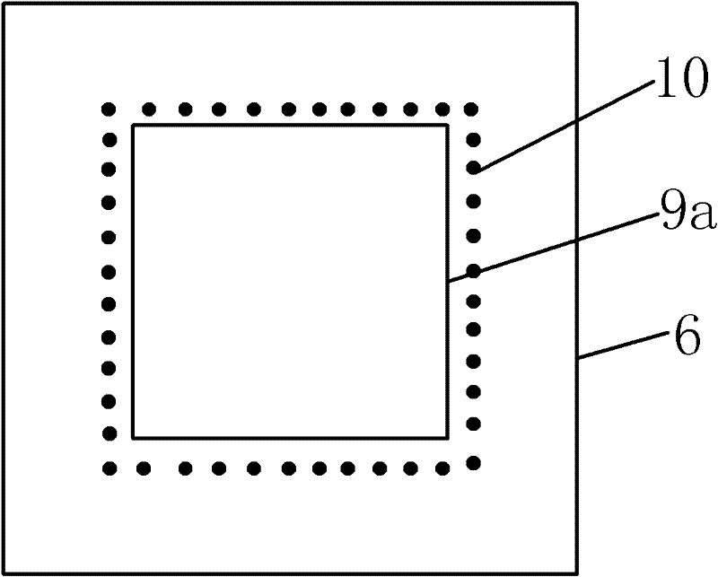
[0023] figure 1A schematic diagram of the configuration and structure principle of the experimental test device for simulating the internal heat transfer mechanism of multi-layer protective clothing is provided; figure 2 It is a structural schematic diagram of the sweating plate 16; image 3 It is a structural schematic diagram of the front splint 6 of the sample; Figure 4 It is a schematic diagram of the structure of the rear splint 8 of the sample. As shown in the accompanying drawings, the present invention simulates the experimental test device of the internal heat transfer mechanism of multi-layer protective clothing, including a heat source (2) whose cooling surface is a vertical plane, a preheating shielding plate (3), a water spray system (12 ), the sample front splint (6), the sample rear splint (8), the sweating system (14) and the measurement and control system (19); There are sample holes (9a) and (9b) which are similar in shape to the periphery of the tested ...
Embodiment 2
[0032]In this embodiment, the tested sample (7) with thermocouples installed on each layer is placed on the sample bottom plate (6C), and the sample positioning needle (10) on the sample bottom plate (6C) passes through the tested sample (7) In the present embodiment, pads are not added on the fixed rod (33), but the fixed rod hole (39) around the sweating plate (16) is directly penetrated into the fixed rod (33), and each fixed rod (33) Tighten the screws. At this time, the tested sample (7) is located between the sweating plate (16) and the sample bottom plate (6C), the tested sample (7) is close to the sweating plate (16), and the tested sample (7) is in contact with the sweating plate ( 16) The air layer gaps between and between layers of fabrics are all 0. The sample installation method of this embodiment can simulate the heat transfer inside the fabric when the fabric is close to the skin.
Embodiment 3
[0034] Heat source (2) among the present embodiment adopts resistance wire heater, and the resistance wire that diameter is 3mm is wound on 460mm long, and diameter is on 12 carbon rods of 25mm, and the carbon rod (25) that has wound resistance wire is mutually spaced 25mm , framed in parallel in the heat-insulating frame (24) perpendicular to the bottom plate (1), forming a heat-dissipating surface with a vertical plane and a heat-dissipating area of 625mm×460mm, and the heat flow intensity is 15kw / m 2 . After passing each layer of the sample to be tested (7) through the sample positioning needle (10) on the sample bottom plate (6C), add a gasket with an inner diameter of 1mm and a thickness of 2mm on each sample positioning needle (10) , after each layer of samples is fixed, insert the fixing rod holes (39) around the sample rear splint (8) into the fixing rods (33), and screw on each fixing rod (33); When the valve of the water system (12) is closed, the effect of human ...
PUM
| Property | Measurement | Unit |
|---|---|---|
| Thickness | aaaaa | aaaaa |
| Diameter | aaaaa | aaaaa |
| Diameter | aaaaa | aaaaa |
Abstract
Description
Claims
Application Information