
Permanent magnet linear generator

A permanent magnet linear and generator technology, applied in the direction of electrical components, electromechanical devices, etc., can solve the problems of large bearing force, low power density, and large unilateral magnetic pull, and achieve simple and convenient air gap adjustment and increased power density. The effect of large and small friction loss

Active Publication Date: 2011-09-14
中国船舶重工集团公司第七一二研究所
View PDF4 Cites 2 Cited by
  • Summary
  • Abstract
  • Description
  • Claims
  • Application Information

AI Technical Summary

Problems solved by technology

Generally, the permanent magnet linear generator adopts a unilateral motor structure, and the unilateral magnetic pull of the mover and stator is large. Especially in the direct-drive wave energy generation system, due to the low linear speed, the motor's The size is large, and the unilateral magnetic pull is large. The use of the traditional structure will cause the bearing to be stressed, wear quickly, often need maintenance, and the power density is also small; this conventional overall structure has a single installation method for the mover and stator, and the mover and The adjustment of the air gap between the stators is not flexible enough, these problems need to be solved in the structural design

Method used


Image

  • Permanent magnet linear generator
  • Permanent magnet linear generator
  • Permanent magnet linear generator

Examples


Embodiment Construction

[0023] The present invention will be further described below in conjunction with accompanying drawing and embodiment:

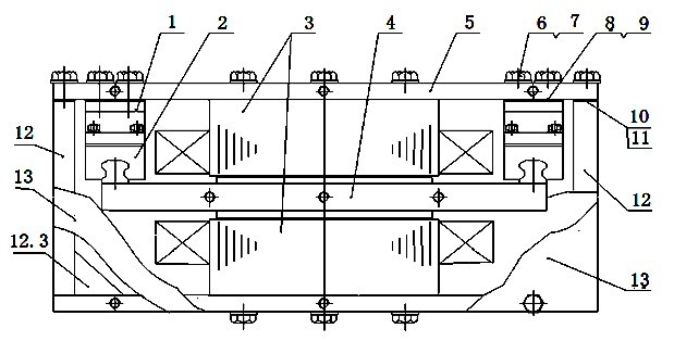
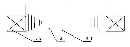
[0024] As shown in the figure, a permanent magnet linear generator has a stator 4 and a mover 3; the stator 4 is composed of a permanent magnet 4.1 and a mover yoke 4.2, and the upper and lower sides of the mover yoke 4.2 are glued with Permanent magnet 4.1; mover 3 is composed of mover iron core 3.1 and coil 3.2, the coil 3.2 is embedded in the slot of mover iron core 3.1; said mover 3 has two, respectively arranged symmetrically on the stator 4 On the side and the lower side; the mover iron core 3.1 is composed of a mover punch 3.11, and the mover punch 3.11 is provided with a wedge-shaped groove 3.12 for the pull rod to pass through, and the pull rod passes through the fastener and the cover plate 5 and the machine. The shell 12 is connected to realize the positioning connection of the mover 3 arranged on the upper side and the lower side of the stator 4 ,...


PUM


Abstract

The invention relates to a permanent magnet linear generator, and particularly is suitable for a direct-drive wave energy generating system and a hybrid vehicle generating system. The generator comprises a stator and two rotors, wherein the stator comprises permanent magnets and a rotor yoke; the top surface and the lower surface of the rotor yoke are adhered to the permanent magnets; each rotor comprises a rotor iron core and a coil; the coil is embedded into the slot of the rotor iron core; and the two rotors are symmetrically arranged on the upper side face and the lower side face of the stator respectively. According to the generator, the number of the bearings of the two motors is halved, bearing force is zero, an air gap is adjusted concisely and conveniently, and friction loss is small; and particularly, according to the technical scheme of the generator with a symmetrical structure, a symmetrical structure with four motors or six motors can be formed, thus a permanent magneticlinear generator with higher motor efficiency can be obtained.

Description

technical field [0001] The invention relates to a permanent magnet linear generator, which is especially suitable for a direct-drive wave energy power generation system and a hybrid electric vehicle power generation system. Background technique [0002] With the continuous expansion of the application range of linear generators, the structural types of conventional linear generators must be continuously developed and innovated to meet the needs of different application fields. Generally, the permanent magnet linear generator adopts a unilateral motor structure, and the unilateral magnetic pull of the mover and stator is large. Especially in the direct-drive wave energy generation system, due to the low linear speed, the motor's The size is large, and the unilateral magnetic pull is large. The use of the traditional structure will cause the bearing to be stressed, wear quickly, often need maintenance, and the power density is also small; this conventional overall structure ha...

Claims


Application Information

Patent Timeline
IPC IPC(8): H02K35/04
Inventor 肖阳胡国葆谌瑾贾海媛
Owner 中国船舶重工集团公司第七一二研究所
Learn More