Laser communication system

A laser and subsystem technology, applied in electromagnetic transceivers, free space transmission, line-of-sight transmission, etc., can solve problems such as difficulty in faster speed, difficulty in adjusting vibration, difficulty in continuous communication between communication links, etc., to achieve improved stability performance, fast capture, overcoming the effects of bumps and vibrations

Active Publication Date: 2015-01-07
北京国科环宇科技股份有限公司
View PDF2 Cites 0 Cited by
  • Summary
  • Abstract
  • Description
  • Claims
  • Application Information

AI Technical Summary

Problems solved by technology

However, the APT system included in the existing laser communication system realizes the rotation of the optical transceiver antenna 14 through the motor and the mechanical turntable inside the APT system. Due to the large moment of inertia of the optical transceiver antenna 14 and the mechanical turntable, it is difficult to achieve a faster speed. , higher frequency rotation, which makes it difficult for the communication link between the two parties to achieve continuous communication; at the same time, although the system for targeting and tracking contained in the APT system can achieve fast tracking, due to the field of view and range of change Smaller, it is difficult to adjust for larger vibrations, so the existing laser communication system needs to be further improved

Method used


Image

  • Laser communication system
  • Laser communication system
  • Laser communication system

Examples


Embodiment Construction

[0057] In order to make the object, technical solution, and advantages of the present invention clearer, the present invention will be further described in detail below with reference to the accompanying drawings and examples.

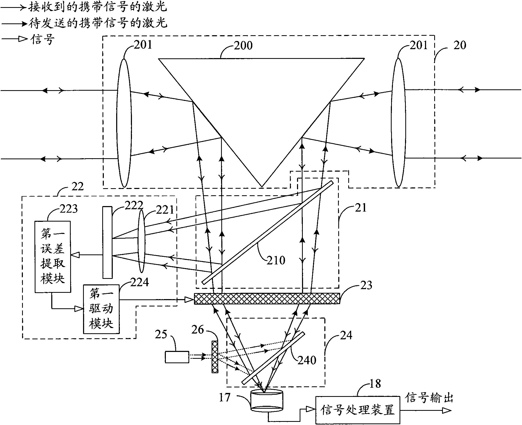
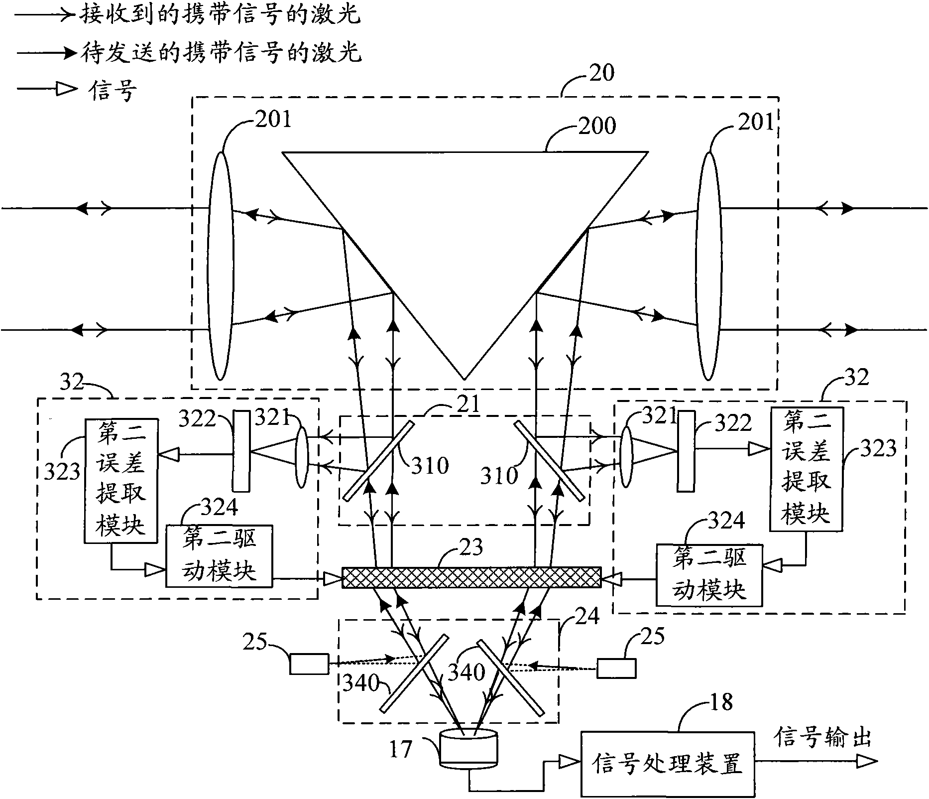
[0058] figure 2 It is a schematic structural diagram of Embodiment 1 of the laser communication system of the present invention. Fig. 4(a) is a perspective view of the optical antenna of the laser communication system of the present invention. Fig. 4(b) is a top view of the optical antenna of the laser communication system of the present invention. FIG. 4( c ) is a schematic structural view of the regular polygonal pyramid reflector included in the omnidirectional optical transceiver antenna of the present invention. Figure 5 It is a schematic diagram of the partitions of the spatial light modulator of the laser communication system of the present invention. Combine now figure 2 , Figure 4(a), Figure 4(b), Figure 4(c) and Figure 5 , to describ...


PUM


Abstract

The invention provides a laser communication system. In the system, an omni-directional optical transceiver antenna receives external lasers carrying signals; the optical path of the lasers carrying signals is adjusted; partial lasers are reflected to a tracking sub-system through a first light split sub-system; partial lasers are transmitted to a first focusing sub-system; the received laser to be transmitted, which carries signals and is transmitted by the first light split sub-system, is changed to be parallel light and exits; the tracking sub-system collects position images of the lasers carrying signals and reflected by the first light split sub-system, an offset is calculated according to the position images and the center point of image collection, and the position of the first focusing sub-system is controlled according to the offset, so that the lasers transmitted by the first focusing sub-system injects into a photoelectric detector through a second light split sub-system. By adopting the system, quick capture can be realized, a communication link capable of continuously communicating is established, the influence of great vibration to the communication link is reduced, and the stability of the communication link is improved.

Description

technical field [0001] The invention relates to laser radar technology, in particular to a laser communication system. Background technique [0002] Because the laser has the advantages of extremely short wavelength and high frequency, coupled with the characteristics of laser coherence, monochromaticity and directivity, the laser communication system has the following advantages compared with other communication systems: (1) communication capacity Large, the available bandwidth of the laser communication system is 105 times that of the radio frequency band, and the modulation bandwidth of the laser communication can reach 40Gbit / s; (2) The system size, quality and power consumption are significantly reduced. Because the laser wavelength is very short, the system uses The size of the device is significantly reduced, and the quality and power consumption are also reduced. For example: the effective gain of a 15.24cm optical transmitting antenna is 122dB, while the effective g...

Claims


Application Information

Patent Timeline
Patent Type & Authority Patents(China)
IPC IPC(8): H04B10/11H04B10/112H04B10/40
Inventor 牛春晖董鹏刘明刘洋
Owner 北京国科环宇科技股份有限公司
Why Eureka
Try Eureka