Map type visible control system for LED (Light Emitting Diode) lamps

A technology of LED lamps and control systems, which is applied in the direction of energy-saving control technology, lamp circuit layout, light source, etc., can solve problems such as corresponding relationship troubles, and achieve the effects of reducing power consumption, maximizing energy utilization, and facilitating life

Inactive Publication Date: 2011-09-14
HUAZHONG UNIV OF SCI & TECH
View PDF5 Cites 24 Cited by
  • Summary
  • Abstract
  • Description
  • Claims
  • Application Information

AI Technical Summary

Problems solved by technology

In addition, usually the control switches of multiple lamps are placed in one place, causing use

Method used


Image

  • Map type visible control system for LED (Light Emitting Diode) lamps
  • Map type visible control system for LED (Light Emitting Diode) lamps
  • Map type visible control system for LED (Light Emitting Diode) lamps

Examples


Example Embodiment

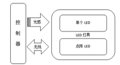
[0037] The invention includes a controller and a control terminal.
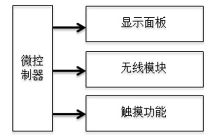
[0038] The controller includes a display panel, metal parts, touch sensor chip, wireless communication module of the main control end, microprocessor and power supply of the main control end, such as figure 2 Shown. The power supply supplies power to other components. The display panel displays the location distribution of the LED lamps in the room in a map mode. If the user wants to operate a lamp in a certain position, he only needs to touch the corresponding position on the interface. In order to sense the user's touch operation, metal parts are placed under the symbol positions of the lamps on the display panel, and touch sensing chips are placed on the sides of the display panel. When the user touches the display interface, the electrical properties (capacitance, resistance, voltage, etc.) of the metal under the touch point change. The touch sensor chip senses the change and converts it into a digital sig...


PUM


Abstract

The invention provides a map type visible control system for LED (Light Emitting Diode) lamps, which comprises a controller and a control terminal, wherein the controller is used for displaying the position distribution of the LED lamps in a room through a map type interface, displaying the current on/off state of the LED lamps in real time, receiving an LED lamp on/off instruction input by a user through the interface in a touched manner, and sending the LED lamp on/off instruction to the control terminal to control the ON and OFF of a corresponding LED lamp. In the invention, as control functions of respective LED lamps in the room are integrated on a handheld controller, and an operating interface is provided in a map type visible manner, the map type visible control system is convenient for the user to operate, and the service efficiency of the LED lamps is increased.

Description

technical field [0001] The invention relates to the field of LED lamp control, in particular to a map-type visual control system for LED lamps. Background technique [0002] Due to the advantages of long life, low power consumption, and good lighting effects, LEDs are gradually used in the field of home lighting. The current LED control switches are mainly embedded in the walls of each room, and users often need to move to operate the lamps. In addition, usually the control switches of multiple lamps are concentrated in one place, causing users to be troubled by the corresponding relationship between the multiple switches and the lamps they control. Contents of the invention [0003] The purpose of the present invention is to provide a visual management system for LED lamps, which integrates the control functions of indoor LED lamps on a hand-held controller, and provides an operation interface in a map-like visual form, which is convenient for users to operate and improv...

Claims


Application Information

Patent Timeline
IPC IPC(8): H05B37/02
CPCY02B20/42Y02B20/40
Inventor 李江晨尹仕朱石超程振
Owner HUAZHONG UNIV OF SCI & TECH
Why Eureka
Try Eureka