Bonding device, ultrasonic transducer, and bonding method

A bonding device and ultrasonic technology, applied in welding equipment, electric solid-state devices, semiconductor devices, etc., can solve the problems of hindering the rotation of the bonding head, too large, etc.

Inactive Publication Date: 2014-03-05
HESSE
View PDF9 Cites 0 Cited by
  • Summary
  • Abstract
  • Description
  • Claims
  • Application Information

AI Technical Summary

Problems solved by technology

It is considered disadvantageous here that the joint head provided with conventional ultrasonic transducers has a high moment of inertia due to its function and design, which would impede the joint head rotation or lead to an excessively large rotary drive

Method used


Image

  • Bonding device, ultrasonic transducer, and bonding method
  • Bonding device, ultrasonic transducer, and bonding method
  • Bonding device, ultrasonic transducer, and bonding method

Examples


Embodiment Construction

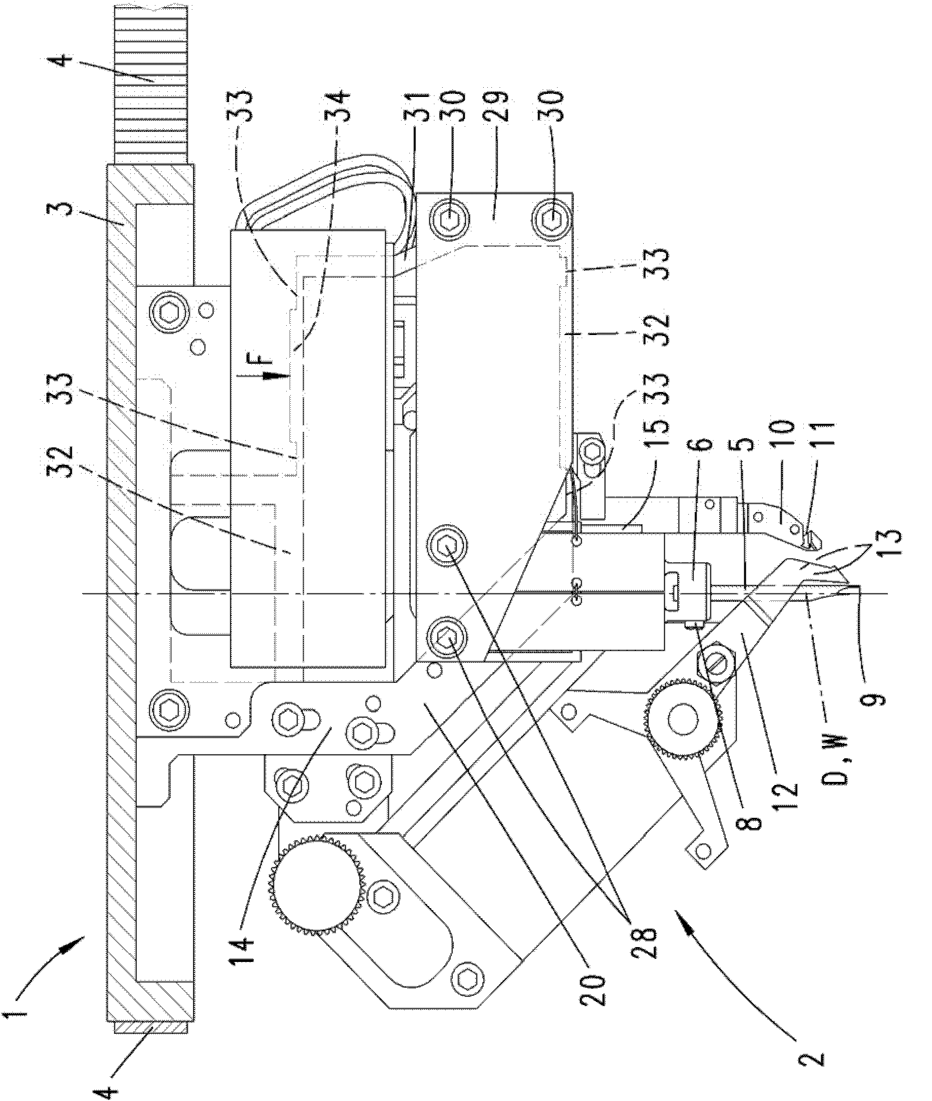
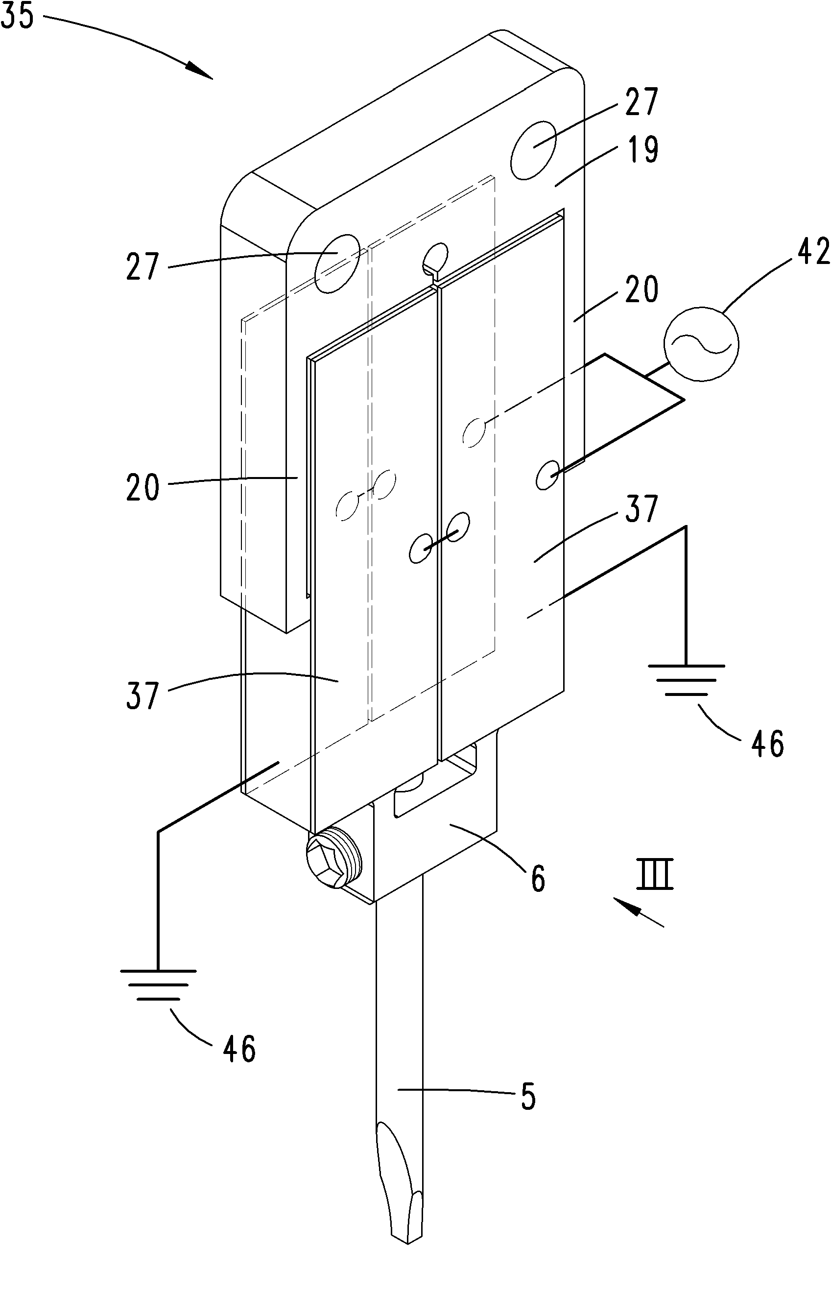
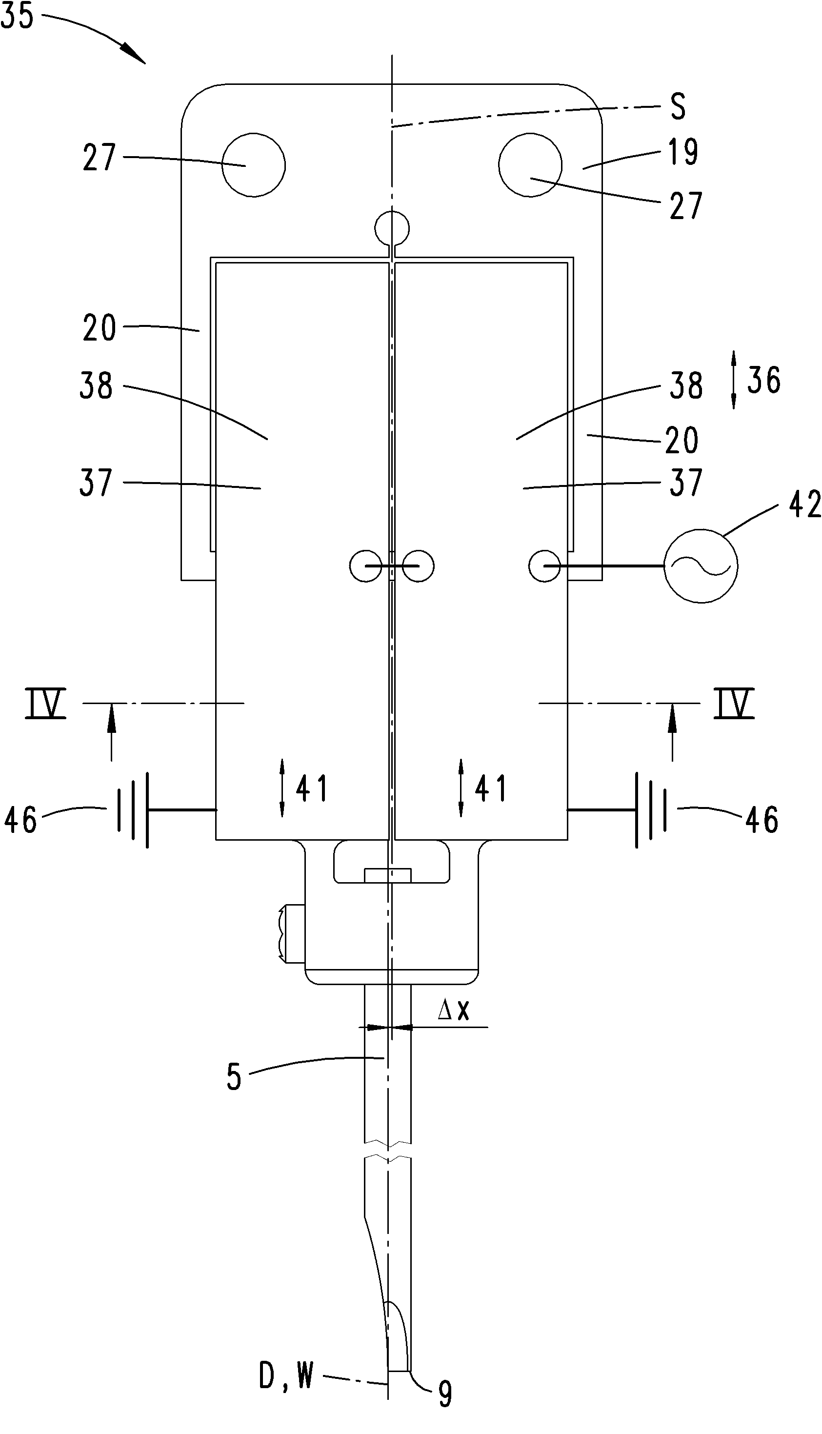
[0042] first reference Figures 1 to 6 A preferred embodiment of the splice device according to the invention and the method according to the invention for establishing a splice connection is described, figure 1 only shows bonding device 1 in the area of ​​bonding head 2, Figures 2 to 6 It is an enlarged view of the components of the bonding head 2. The joint head 2 is fastened on the underside of a wheel 3 , which is rotatable about a vertical axis of rotation D on the joint device 1 in a manner not shown. To generate the rotation, in this embodiment a toothed belt 4 shown only partially can be provided, which meshes with the external toothing of the wheel 3 and which is driven by a driven wheel, not described, wrapped around it by a section according to The desired distance of the corner. An additional driving device can also be provided to make the entire bonding head 2 move laterally in different directions in a plane perpendicular to the rotation axis D. The bonding ...


PUM


Abstract

A bonding device, particularly for producing bond connections between electrical conductors made of wire material or strip material and contact points of substrates such as electrical circuits, wherein the bonding device comprises a bonding head (2) which can be rotated about a geometric axis of rotation (D), in particular a vertical axis, and on which a bonding tool (5) and an ultrasonic transducer (35) are disposed for ultrasonic vibration excitation of the bonding tool (5). It is proposed that the main direction of extension (36) of the ultrasonic transducer (35) and / or the direction of extension thereof in the direction of the axis of the minimum moment of inertia extends parallel to the geometric axis of rotation (D) of the bonding head (2). The invention further relates to a bonding device or an ultrasonic transducer.

Description

technical field [0001] According to a first aspect, the present invention relates to a bonding device, in particular for establishing a bonding connection between an electrical conductor of a thread-like or strip-shaped material and a contact point of a substrate, in particular a circuit substrate, which bonding device has a surrounding preferably A vertical, geometric axis of rotation rotatable joint head, on which a joint tool and an ultrasonic converter for the excitation of ultrasonic oscillations of the joint tool are arranged. Background technique [0002] This type of bonding device generally utilizes a bonding tool (which may be a so-called wedge in a commonly used embodiment) to press the part of the conductor (such as an aluminum wire or gold wire) that needs to be bonded to the substrate (such as a circuit substrate) with a specific pressure. sheet) at the desired contact position, during which the bonding tool oscillates ultrasonic waves transversely to the press...

Claims


Application Information

Patent Timeline
Patent Type & Authority Patents(China)
IPC IPC(8): H01L21/607H01L41/09H01L21/60H01L21/00B23K20/00B23K20/10
CPCH01L2924/01074H01L2224/85205H01L24/85H01L41/12H01L2924/01005H01L24/78H01L2924/01061H01L2924/01082B23K2201/42B23K20/106H01L2224/45144H01L2924/01013B23K20/002H01L2924/01015H01L2924/014H01L21/67138H01L2224/78313H01L2924/01047H01L2224/45124H01L2924/01033H01L2924/01068H01L2924/00014H01L2924/01079H01L41/0906H01L2924/07802B23K2101/42H01L2224/45014H01L2224/48H01L2924/00015H01L2924/00B23K20/10H01L21/00H10N30/20
Inventor H-J·黑塞J·瓦拉斯切克M·布勒克曼P·瓦希杰夫
Owner HESSE
Why Eureka
Try Eureka