
Soy milk making machine

A soymilk maker and pulping technology, which is applied to milk substitutes, beverage preparation devices, household appliances, etc., can solve the problems of insufficient suction, difficult cleaning, and easy wear and tear, and achieve the effect of fine slurry, convenient use, and easy operation

Inactive Publication Date: 2011-09-21
ZHEJIANG SHAOXING SUPOR DOMESTIC ELECTRICAL APPLIANCE CO LTD
View PDF7 Cites 24 Cited by
  • Summary
  • Abstract
  • Description
  • Claims
  • Application Information

AI Technical Summary

Problems solved by technology

After adopting the above structure, the impeller-shaped inner grinding disc can make water and pulping materials flow from top to bottom, and at the same time, water will enter the bean-carrying cup from the water inlet hole to replenish water to the inner grinding disc and outer grinding disc to achieve inward The purpose of automatic water supply and cleaning of the grinding disc and the outer grinding disc; its disadvantages are: first, the beans need to be fed into the pulping container from the feeding channel of the machine base, and the channel is narrow and sticky after heating and cooking, making cleaning difficult; The bean curds produced during the process are thrown out and float on the liquid surface, which cannot be ground circularly; the third is that the initially crushed material sinks to the bottom of the container due to gravity, and the inner grinding disc is far away from the bottom of the container, which cannot produce enough grinding from the outside to the inside. The suction force, the fluid that forms the circulation is very limited, and it is impossible to achieve circular grinding
At the same time, the fixing method of the motor is easy to swing and vibrate when the motor is working, which will affect the life of the motor and also cause dangers such as machine overturning.
[0005] With the development and innovation of soybean milk machine technology, a kind of axial flow grinding soybean milk machine is also introduced. For example, the utility model patent with the notification number CN201479858U discloses another bladeless axial flow soybean milk machine, which includes an organic seat, an anti-overflow electrode, and a temperature sensor. , electric heating tube, barrel body, motor, motor shaft; the lower cover of the machine base is buckled on the barrel body, and also includes a crushing body installed on the motor shaft, and a pulverizer fixed on the machine base and located outside the crushing body; There are discharge holes on the device, and there are crushing grooves on the outer wall of the pulverizer and the inner wall of the pulverizer, and the edges are relatively sharp. This technical solution solves the problem of pulping fluid circulation, but other shortcomings are also obvious: First, the structure is only tight The pulverizing groove on the crushing body stirs the water flow to generate suction, which drives the food into the pulverizer. When pulverizing larger food, it will encounter the problem of insufficient suction; The food is stuck between the pulverizer and the pulverizer, which will seriously affect the life of the motor and the performance of the whole machine; the third is that the pulverizer relies on the sharpness of the edge of the protrusions between adjacent pulverization grooves to increase the pulverization. As a result, this sharp edge is easy to be worn, and there is a dead angle in cleaning, which is easy to hurt hands; the fourth is that the crushing groove of the technical solution is a plurality of non-intersecting grooves along the grinder or crushing with equal or unequal intervals. The outer wall is distributed in a spiral or straight line, which is not conducive to crushing from coarse to fine, and its minimum gap of 5mm is too large, so it is difficult to achieve fine crushing of soybean milk particles. After the food is less than 5mm in size, it can only be driven by limited suction. , resulting in collisions to achieve crushing, which does not achieve the original intention of relying on rolling to realize the grinding and crushing design; fifth, it is quite difficult to realize the production process of making spiral grooves on the outside of the pulverizer and on the inner wall of the pulverizer, even if the cost is realized. It is also quite high, unable to form industrialized mass production and popularization of products

Method used


Image

  • Soy milk making machine
  • Soy milk making machine
  • Soy milk making machine

Examples


Embodiment 2

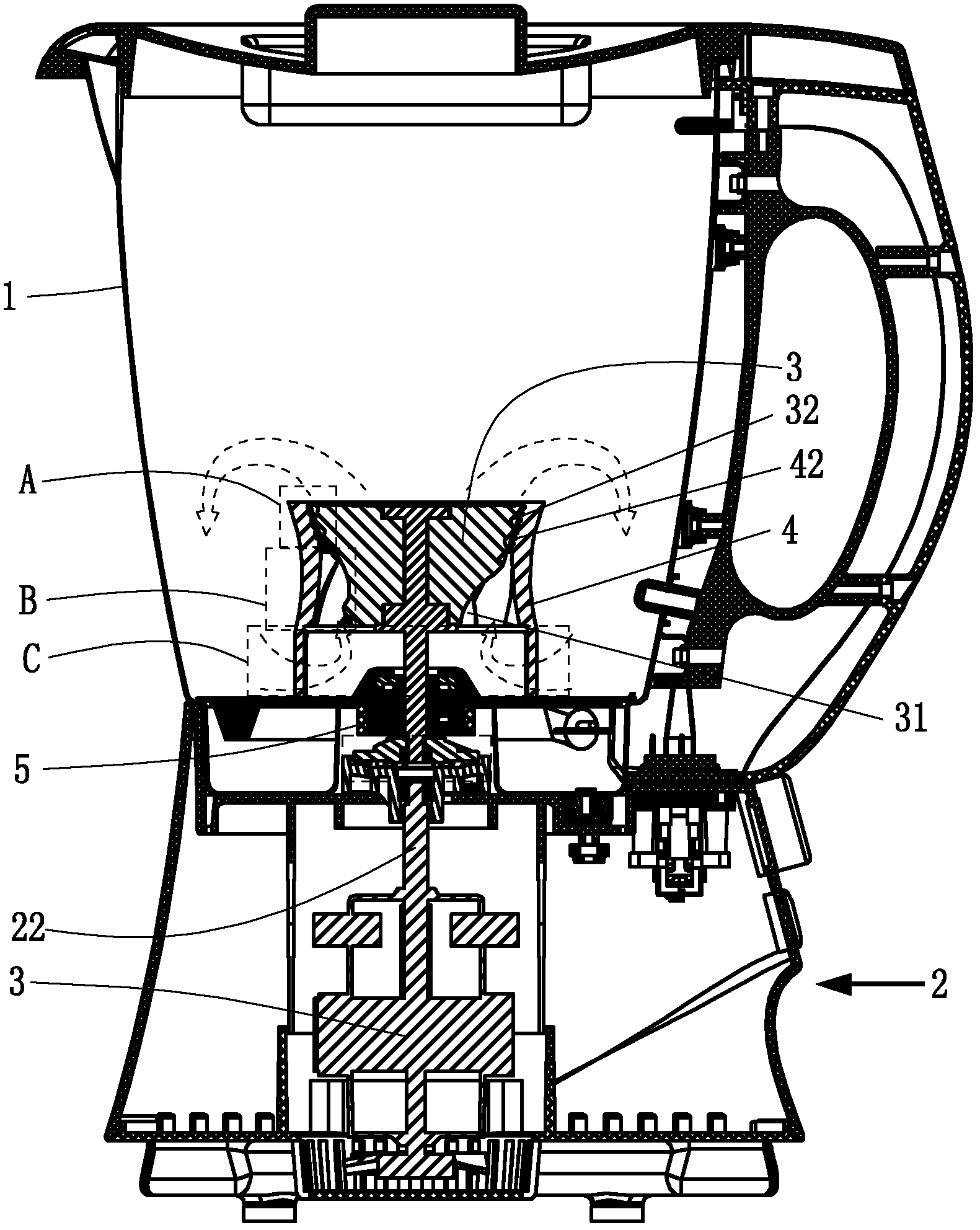
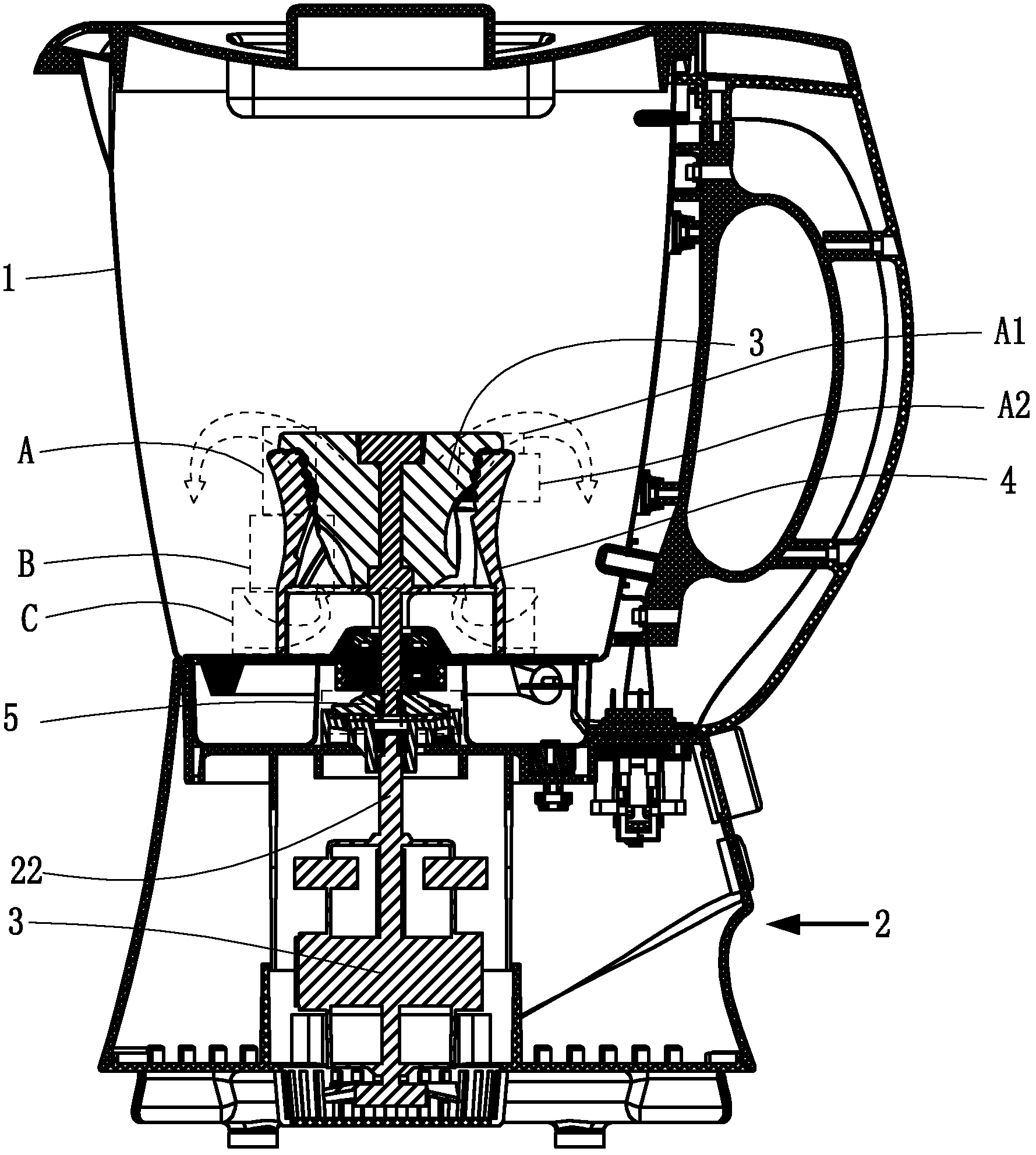
[0058] See attached Figure 2~4 , The dynamic and static grinding heads of this embodiment are different from those of Embodiment 1, and have the same technical effects as Embodiment 1 in other places, so they will not be repeated here.

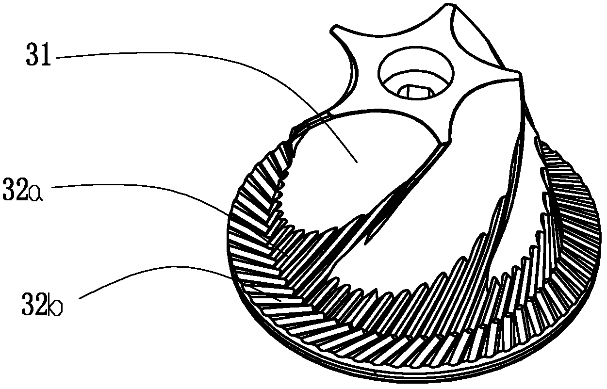
[0059] In this embodiment, the dynamic and static grinding heads are further divided into a rough grinding part A1 and a fine grinding part A2 in the grinding part A, and the moving grinding head 3 is respectively provided at the guide part B, the rough grinding part A1 and the fine grinding part A2. There are movable grinding guide teeth 31, dynamic grinding coarse grinding teeth 32a and dynamic grinding fine grinding teeth 32b.

[0060] The static grinding head 4 is provided with a static grinding guide tooth 41 , a static grinding rough grinding tooth 42 a and a static grinding fine grinding tooth 42 b at the material guide part B, the rough grinding part A1 and the fine grinding part A2 respectively.

[0061] The dynamic grinding guide t...

Embodiment 3

[0064] See attached Figure 5~7 , The dynamic and static grinding heads of this embodiment are different from those of Embodiment 1, and have the same technical effects as Embodiment 1 in other places, so they will not be repeated here.

[0065] In this example,

[0066] The movable grinding guide tooth 31 is a rotating member capable of generating liquid flow when rotating, specifically, the movable grinding guide tooth 31 is a propeller-shaped blade.

[0067] The working surfaces of the movable grinding head 3 and the static grinding head 4 at the grinding part A are roughly disc-shaped.

[0068] The dynamic grinding head 3 is provided with a dynamic grinding material guide hole 33 connecting the working surface with the outside. When grinding, when encountering large particles or materials that are difficult to grind and pulverize, the materials will be sent to the dynamic grinding material guide hole 33 and then flow out of the grinding area. It prevents the motor from ...

Embodiment 4

[0070] See attached Figure 8~10 , The dynamic and static grinding heads of this embodiment are different from those of Embodiment 1, and have the same technical effects as Embodiment 1 in other places, so they will not be repeated here.

[0071] In this embodiment, the dynamic grinding guide teeth 31, the dynamic grinding coarse grinding teeth 32a, the dynamic grinding fine grinding teeth 32b, the static grinding guide teeth 41, and the static grinding coarse grinding teeth 42a are provided on the dynamic and static grinding heads. The structure of the static grinding and fine grinding teeth 42b is generally a corresponding spiral tooth shape, and the gap between the moving grinding head 3 and the static grinding head 4 between the working surfaces of the rough grinding part A1 and the fine grinding part A2 is from bottom to bottom. gradually becomes smaller, and the gap between the moving grinding head 3 and the static grinding head 4 on the working surface of the material g...


PUM

PropertyMeasurementUnit
Pitchaaaaaaaaaa

Abstract

The invention belongs to the field of small kitchen electric appliances and particularly relates to a soy milk making machine. The soy milk making machine comprises a milk making container and a base arranged under the milk making container, a motor arranged in the base is provided with a motor shaft extending in the milk making container, a movable grinding head is fixedly arranged on the bottomend of the motor shaft, and a static grinding head which is matched with the movable grinding head is fixed in the milk making container. When in fitting, the movable grinding head is arranged in an annular closed space of the static grinding head. The movable grinding head is in detachable connection with the motor shaft. The soy milk making machine has the advantages that the motor is arranged in the base, so that the motor is stable, vibrates slightly and produces low noise during work; the movable grinding head can be provided with different movable grinding guide teeth according to different grinding materials, so that the soy milk making machine is convenient to use and can adapt to the grinding of different materials; primary grinding, coarse grinding and fine grinding can be respectively realized with different screw teeth or grinding teeth, so that milk is finer and smoother and has higher concentration; besides, the movable grinding head and the motor shaft are in detachablestructures, a shaft coupling is arranged between the movable grinding head and the motor, and the movable grinding head can be freely detached and changed and is easy to clean.

Description

[0001] technical field [0002] The invention belongs to the field of small kitchen appliances, and in particular relates to a soybean milk maker. Background technique [0003] At present, soybean milk machine, as a kind of commonly used household appliance, has gradually entered the households of ordinary people. The pulping method of soybean milk machine on the existing market is generally to connect a crushing tool to the motor in the machine base, and cooperate with the crushing tool to achieve crushing. The structure of pulping mainly has the following two types: the first one is to set a turbulence net at the bottom of the machine base, and the crushing cutter is set in the turbulence net, and the pulverization knife realizes pulping by circulating and whipping in the small space of the turbulence net. The purpose of pulping; the second is to set some disturbing flow ribs on the inner wall of the pulping container, and when the crushing cutter rotates, it will drive th...

Claims


Application Information

Patent Timeline
IPC IPC(8): A47J31/00A47J31/44A23C11/10
Inventor 蔡才德张锦洲陈世雄湛海耀
Owner ZHEJIANG SHAOXING SUPOR DOMESTIC ELECTRICAL APPLIANCE CO LTD
Learn More