Paddle floating-type stirring machine

A floating type, mixer technology, applied in mixers, mixers, dissolving and other directions with rotary stirring devices, can solve the problems that it is difficult to achieve uniform distribution and wall hanging of feeding materials, and achieve simple structure, convenient processing and improved efficiency. obvious effect

Inactive Publication Date: 2011-09-21
董保成 +1
View PDF5 Cites 22 Cited by
  • Summary
  • Abstract
  • Description
  • Claims
  • Application Information

AI Technical Summary

Problems solved by technology

For materials with poor fluidity, it is difficult to achieve uniform distribution of the feed, and a large area of ​​accum

Method used


Image

  • Paddle floating-type stirring machine
  • Paddle floating-type stirring machine
  • Paddle floating-type stirring machine

Examples


Embodiment Construction

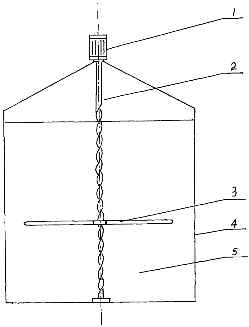
[0017] Such as figure 1 As shown, the variable frequency motor (1) can adjust the rotation speed during operation to achieve the purpose of adjusting the position of the blade.

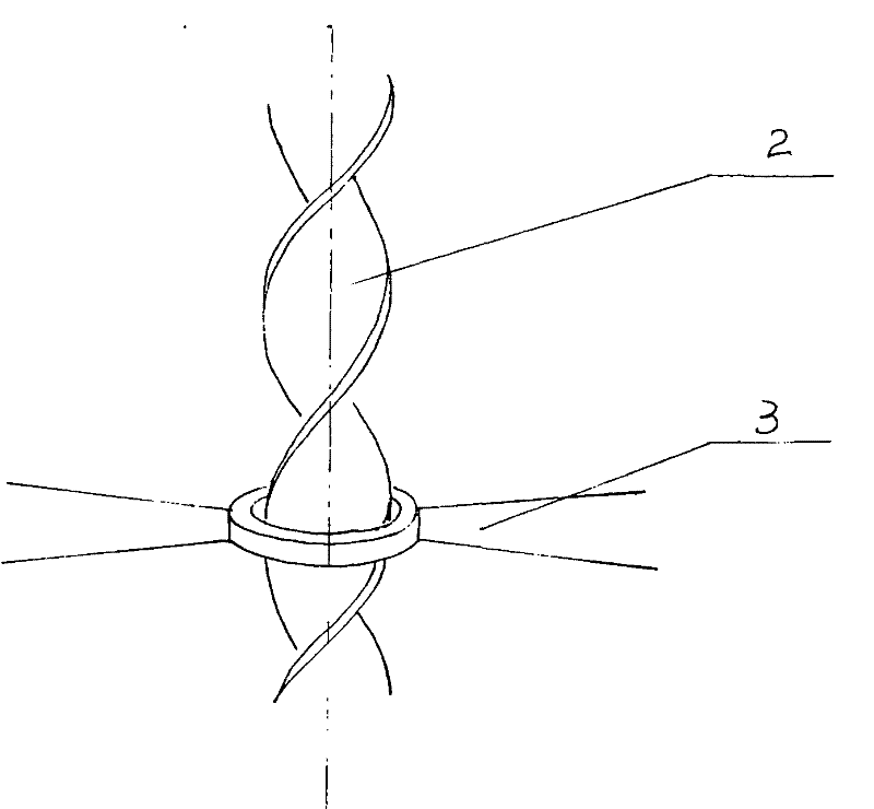
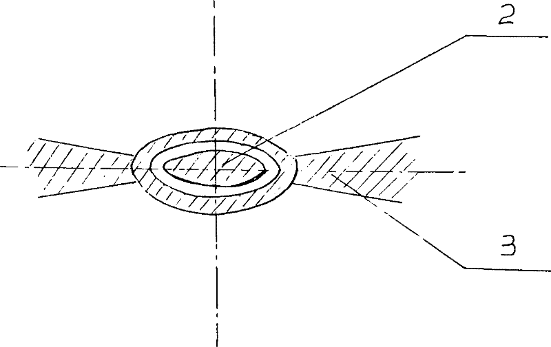
[0018] When the screw shaft (2) stops or the speed slows down, the floating stirring blade (3) will slide down or move up along the screw shaft (2) due to the influence of gravity and buoyancy only, and finally suspend in the solid-liquid mixture ( 5) the surface or bottom;

[0019] When the screw shaft (2) rotates rapidly, the floating stirring blade (3) is subjected to tangential force, and the floating stirring blade (3) will move along the screw shaft (2) depending on the direction of rotation of the screw shaft (2). direction movement;

[0020] Through the above two states, the movement up and down in the tank can be realized.


PUM


Abstract

The invention relates to a paddle floating-type stirring machine. The stirring machine mainly comprises a variable frequency motor (1), a spiral shaft (2), a floating-type stirring paddle (3), wherein the variable frequency motor (1) and the spiral shaft (2) are in a fixed connection state, the spiral shaft (2) and the floating-type stirring paddle (3) are assembled and are in a free sliding state along the spiral shaft (2). The stirring machine is mainly arranged in a fermentation tank body (4) or other containers and is used for uniformly distributing and stirring solid-liquid mixed materials (5); the floating-type stirring paddle (3) can move up and down along the spiral shaft (2) along with variation of rotating speed of the variable frequency motor (1), thus the problem that materials can not be stirred or uniformly distributed at different parts as required as the paddle is fixed in the traditional stirring machine can be effectively solved; and the problems that gas production is influenced, material distribution is nonuniform and stirring is nonuniform as the materials crust in the fermentation tank body (4) or containers can be effectively solved, the structure is compact, the stirring effect is full, and the product cost is low. The stirring machine provided by the invention is mainly used in fermentation and related industries.

Description

technical field [0001] The invention relates to a stirring and distributing equipment, in particular, it is suitable for uniform distributing and stirring of a fermentation tank body. Background technique [0002] At present, fixed mixers are used for the distribution and stirring in the fermentation tank or container, and the material will naturally be divided into four layers due to density, from top to bottom into a scum layer, a supernatant, an active layer and a sediment layer. In this case, the place where the microbial activity is more vigorous is only in the active layer, while the other layers will have a lack of materials or are not suitable for microbial growth activities, which makes the sludge concentration inside the reaction tank or container uneven. At the same time, the stratification of the material also makes the temperature distribution inside the container uneven. Based on the above situation, the existing fermenter or container adopts the mode of addin...

Claims


Application Information

Patent Timeline
IPC IPC(8): B01F7/18
CPCY02P70/10
Inventor 董保成陆军平
Owner 董保成
Why Eureka
Try Eureka