Supercharge Your Innovation With Domain-Expert AI Agents!

Spiral rock splitter

A technology of spiral rock and splitting machine, applied in the field of rock splitting machine, can solve the problems of long production cycle, heavy equipment and high production cost, and achieve the effects of convenient transportation and use, easy assembly and maintenance, and energy saving and energy consumption.

Inactive Publication Date: 2011-09-21
SHANGHAI VAMEN IND
View PDF0 Cites 2 Cited by
  • Summary
  • Abstract
  • Description
  • Claims
  • Application Information

AI Technical Summary

Problems solved by technology

[0008] complex structure;
[0009] High production cost and long production cycle;
[0010] Due to the limitation of use occasions, due to the bulky equipment, it is powerless in places with inconvenient transportation, difficult to operate and small spaces;
[0011] The use cost is high, and the hydraulic station should be equipped with a large-power electric motor or internal combustion engine as power, plus there are many components and wearing parts, and the maintenance and use costs are high
[0012] Insufficient in terms of safety and environmental protection, high-pressure hydraulic oil may leak oil through control valves, oil pipes, joints, oil cylinders, etc., causing losses and environmental pollution, joints and oil pipes may also be thrown off high-pressure hydraulic oil, which constitutes a safety hazard for operators certain danger

Method used


Image

  • Spiral rock splitter
  • Spiral rock splitter

Examples


Embodiment Construction

[0018] Below in conjunction with accompanying drawing and specific embodiment the present invention is described in further detail:

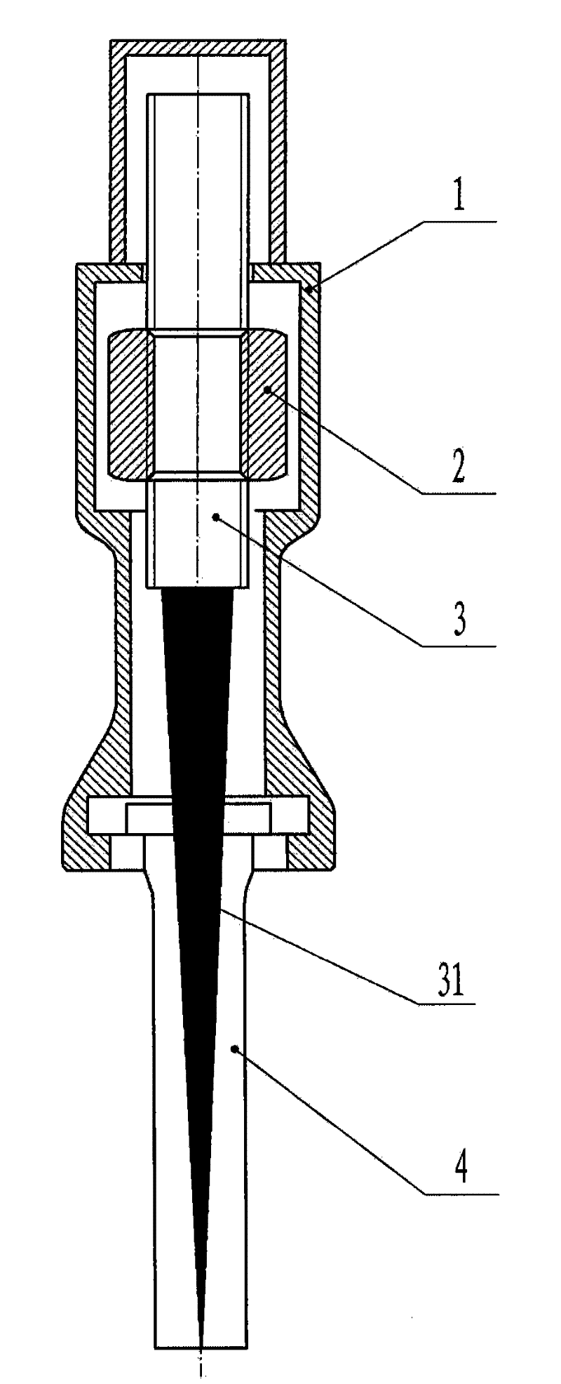
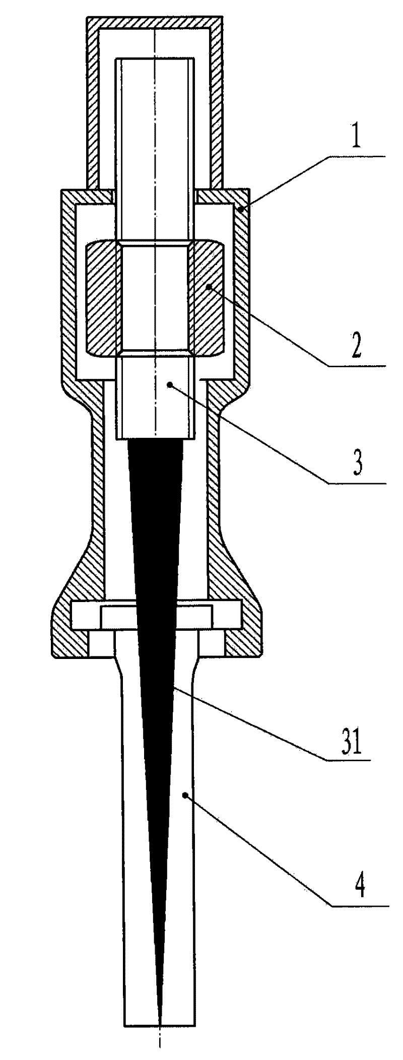
[0019] The present invention includes: a cage 1; a nut 2 is placed in the inner cavity of the cage 1; a screw 3 is placed in the middle of the nut 2; the screw 3 is connected to the middle wedge 31 at its lower end or the middle wedge 31 is connected to the nut 2 are connected; the side wedges 4 are arranged on both sides of the middle wedge 31.

[0020] In the structure of the present invention, the nut 2 rotates around the central axis, and the screw mandrel 3 can move up and down in a straight line without being able to rotate; it is also possible to allow the screw mandrel 3 to perform a rotational movement, while the nut 2 moves linearly along the central axis, so as to achieve the same driving structure effect. The screw rod in the structure of the present invention can be a threaded screw rod or a ball screw rod.

[0021] Through manual,...


PUM


Abstract

The invention relates to a spiral rock splitter, which comprises a retainer; a nut is placed in the cavity of the retainer; a lead screw is placed in the middle of the nut; the lead screw is connected with a middle wedge block at the lower end thereof, or the middle wedge block is connected with the nut; and side wedge blocks are arranged on two sides of the middle wedge block. The spiral rock splitter has the advantages that: the weight is greatly lightened, materials and energy consumption are saved, and transportation and use are extremely convenient; the spiral rock splitter has a few parts and simple structure, is easy to manufacture, assemble and maintain, and has low using cost; high-pressure hydraulic oil is not needed; and the spiral rock splitter has no pollution to the environment, has no danger to operators, and is very good equipment for replacing explosive and safe static blast.

Description

technical field [0001] The present invention relates to a rock splitter, in particular to the structure of the driving mechanism of the rock splitter. Background technique [0002] All kinds of rock ore and concrete have high compressive strength, but their tensile strength is small. The hydraulic rock splitter is designed according to the brittleness of rock and concrete, using the wedge principle. [0003] The main application occasions of the hydraulic rock splitter are: mining of various stone materials, crushing and demolition of rocks and concrete in construction occasions, secondary splitting of large rocks, ores, and concrete, emergency rescue and other special construction occasions. [0004] The hydraulic rock splitter is mainly composed of two parts: the driving mechanism and the splitting gun. [0005] Products on the market in the prior art are composed of hydraulic station (made up of electric motor or internal combustion engine or air motor and hydraulic pump...

Claims


Application Information

Patent Timeline
Patent Type & Authority Applications(China)
IPC IPC(8): E21C37/02B28D1/22
Inventor 梁汉根禤海明梁善军
Owner SHANGHAI VAMEN IND
Features
  • R&D
  • Intellectual Property
  • Life Sciences
  • Materials
  • Tech Scout
  • Unparalleled Data Quality
  • Higher Quality Content
  • 60% Fewer Hallucinations
Learn More