Driving device of engine brake

A driving device and brake technology, applied in the direction of engine components, machines/engines, valve devices, etc., can solve the problems of large inertia of the braking system, slow response, increased engine height and manufacturing cost, etc., to reduce costs and reduce requirements. , the effect of reducing the braking reaction time

Active Publication Date: 2011-09-21
SHANGHAI UNIVERSOON AUTOPARTS CO LTD
View PDF5 Cites 5 Cited by
  • Summary
  • Abstract
  • Description
  • Claims
  • Application Information

AI Technical Summary

Problems solved by technology

[0006] The purpose of the present invention is to provide a novel engine braking device, which solves the technical problem that the overhead mode of the engine braking system in the prior art increases the height of the engine and the manufacturing cost, At the same time, it is necessary to solve the technical problems of large inertia and slow response of the braking system existing in the hydraulically driven engine brake

Method used


Image

  • Driving device of engine brake
  • Driving device of engine brake
  • Driving device of engine brake

Examples


Embodiment 1

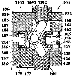
[0023] Such as figure 1 As shown, a driving device 100 for an engine brake of the present invention is composed of a brake box 2102, an upper connecting rod 186, a lower connecting rod 186 with the same structure, and a driving piston 162, and the driving piston 162 is located in the braking box. In the horizontal piston hole 260 of 2102, it is usually pushed to the left by the return spring 156, and rests on the end surface 246 of the piston hole 260. The other end of the return spring 156 is located on the spring seat 158 ​​, and the spring seat 158 ​​is positioned by the retaining ring 157 fixed on the brake case 2102 . In the middle of the driving piston 162, there is a cutout 137 as a guide groove. The width of the guide groove 137 is approximately the same as the diameter of the upper connecting rod and the lower connecting rod 186. At the left end of the horizontal hole 260, the inclinations of the upper link and the lower link 186 are approximately the same. There is...

Embodiment 2

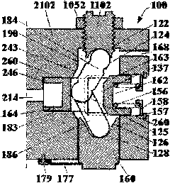
[0028] Such as figure 2As shown, the driving mechanism 100 of this embodiment is an evolution of the first embodiment. The drive pistons include a right drive piston 162 and a left drive piston 164 . In this embodiment, the upper connecting rod 184 and the lower connecting rod 186 are still connected by the spherical surface 125, but there is no spherical body and no guide ring is needed. Right drive piston 162 still has guide groove 137, and the width of guide groove 137 is approximately the same as the diameter of two connecting rods 184 and 186, and the right side of guide groove 137 has two chamfers 163, and left drive piston 164 is positioned at the left end of horizontal hole 183. The inclinations of the upper links 184 and 186 are approximately the same. The brake plunger 160 is located in the vertical piston hole 190 of the brake box 2102, and is connected to the third convex spherical surface at the bottom of the lower connecting rod 186 through the third concave s...


PUM


Abstract

The invention provides a driving device of an engine brake. The driving device comprises a braking box body, connecting rods, a driving piston and a braking plunger, wherein a vertical blind hole and a horizontal blind hole which intersect with each other are arranged in the braking box body; the driving piston is arranged in the horizontal blind hole; the braking plunger is arranged at lower part of the vertical blind hole; the connecting rods comprise an upper connecting rod and a lower connecting rod; a revolute pair is arranged between the upper connecting rod and the braking box body; another revolute pair is arranged between the lower connecting rod and the braking plunger; and a fluid channel is arranged in the braking box body to connect the horizontal blind hole with an engine oil fluid network. The driving device has the following beneficial effects: the driving device can be integrated with the engine, thus reducing the height, volume and weight of the engine brake; the hydraulic braking control valve is not needed, thus lowering the cost and reducing the brake response time; the brake load is not borne by liquid, thus enabling the driving device not to be subjected to leakage, deformation and load fluctuation caused by high oil pressure and high oil temperature; and the lift of the brake valve is not affected by the oil temperature and pressure and the air content,thus ensuring that the lift of the brake valve can be a small value, and reducing the requirements for the gap between the engine piston and the air valve.

Description

Technical field: [0001] The invention relates to the mechanical field, in particular to a braking device for an engine, in particular to a driving device for an engine brake. Background technique: [0002] In the prior art, the method of using the internal combustion engine as a braking means is well known, and only the engine needs to be temporarily converted into a compressor. This conversion cuts off the fuel and opens the exhaust valve at or near the end of the engine piston compression stroke, allowing the compressed gas (air during braking) to be released. The energy absorbed by the engine during the compression stroke cannot be used The subsequent expansion stroke returns to the engine piston, but is dissipated through the engine's exhaust and cooling system. The end result is effective engine braking that slows the vehicle. [0003] A precedent for an engine brake is disclosed in US Patent No. 3,220,392 to Cummins, according to which an engine braking system has be...

Claims


Application Information

Patent Timeline
Patent Type & Authority Applications(China)
IPC IPC(8): F01L13/06F01L9/02F01L9/10
CPCF01L2820/00
Inventor 杨洲柯恩九
Owner SHANGHAI UNIVERSOON AUTOPARTS CO LTD
Why Eureka
Try Eureka